
Please Choose Your Language
Views: 0 Author: Site Editor Publish Time: 2026-10-17 Origin: Site


Are distorted edge marks slowing down your production line? I see this constantly on the factory floor. Marking large, bulky, or irregularly shaped industrial parts is a massive bottleneck in modern manufacturing. Traditional methods are painfully slow. They force operators to manually reposition heavy components constantly. This inevitably leads to blurred prints near the edges of the working field.
For production managers and frontline engineers, these physical inefficiencies destroy cycle times and inflate operational costs. The definitive solution to this geometric headache is 3-axis dynamic focusing technology. It completely transforms how massive and complex parts are processed, shifting the burden from mechanical fixtures to intelligent optics.
Dynamic Focus is a Game-Changer: Advanced optics maintain pinpoint focal accuracy across massive surface areas. This completely eliminates the need to physically move the part during the cycle.
No Rotary Needed for Curves: Intelligent 3-axis systems execute seamless processing on cylinders, cones, and uneven planes automatically through software-controlled focal adjustments.
High Power Equals Deep Engraving: High-wattage configurations from 200W to 300W are structurally essential for efficient material removal on industrial molds and dense metals.
Seamless Factory Automation: Modern units integrate standardly with CCD visual positioning cameras. This ensures highly efficient, data-driven, and zero-defect production on automated assembly lines.
Looking at current manufacturing trends, the demand for processing large and non-planar parts is surging rapidly. The electric vehicle and advanced aerospace sectors are driving this massive shift. Lightweighting efforts in these industries have introduced highly complex, aerodynamic part designs. Standard flat marking simply no longer cuts it on the modern shop floor.
Furthermore, facilities are aggressively moving away from multi-step physical fixturing. Instead, they are adopting single-setup optical solutions that adapt to sweeping contours instantly. This transition drastically reduces scrap rates caused by handling errors. It also aligns perfectly with stringent supply chain traceability mandates that require permanent, high-contrast marks on every single manufactured component.
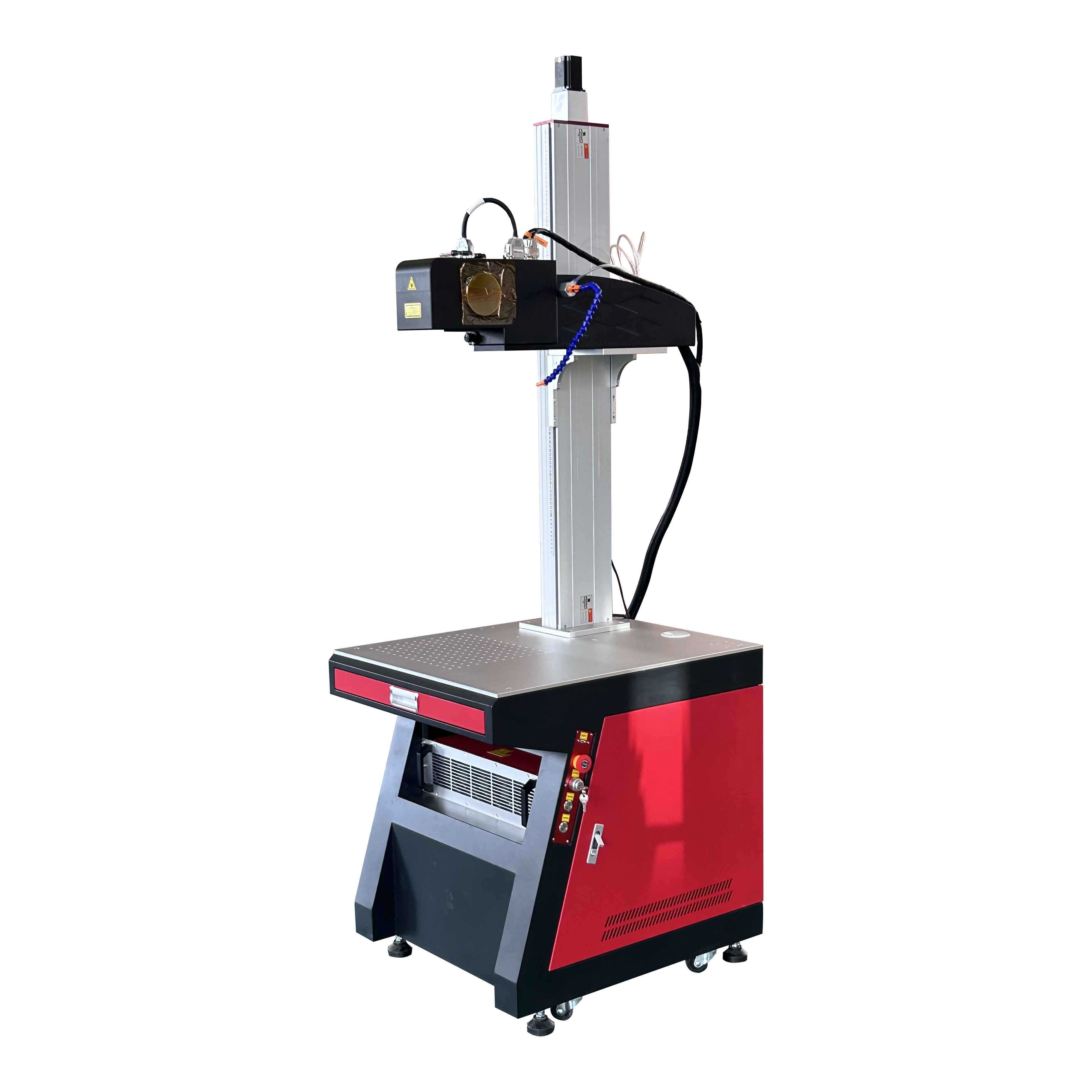
To fully grasp the value of three-dimensional processing, we must first look at the optical physics restricting standard 2D galvo scanners. Traditional setups rely entirely on a fixed F-theta lens. This lens concentrates the beam onto a completely flat, two-dimensional plane. Picture an operator wrestling a 40-pound cast-iron engine block just to keep the target surface perfectly perpendicular to the lens. As the beam sweeps further away from the center toward the perimeter, the distance increases. The focal length naturally extends. Consequently, the spot distorts, loses energy density, and creates shallow marks at the edges.
To compensate for this focal drop-off, manufacturers often implement mechanical XY translation tables. However, dragging heavy parts across physical axes introduces mechanical tolerance errors. It also dramatically increases processing time per unit.
By contrast, a dynamic focusing system resolves this bottleneck optically. It incorporates an independent motorized Z-axis expander before the standard X and Y scanning mirrors. The focal point shifts back and forth in milliseconds. As the beam travels across a massive or uneven surface, this real-time micro-adjustment guarantees the laser spot remains perfectly round and highly concentrated. Ultimately, this eliminates mechanical repositioning and ensures true edge-to-edge consistency.
Technical Aspect | Traditional 2D Galvo Laser | 3-Axis Dynamic Focus System |
|---|---|---|
Working Area | Limited to roughly 300x300mm before severe edge distortion occurs. | Expands flawlessly up to 600x600mm or more with consistent spot size. |
Surface Compatibility | Strictly flat planes. Requires mechanical rotary for cylinders. | Adapts to slopes, steps, and cylinders optically without extra fixtures. |
Processing Speed | Slow for large parts due to mechanical XY table repositioning. | Extremely fast. The beam sweeps the entire massive area in a single setup. |
Edge Quality | Prone to blurred, shallow, or out-of-focus marks at the perimeters. | Maintains high energy density and sharp contrast from center to edge. |
Industrial components rarely feature perfectly flat profiles. Automotive chassis components, aerospace turbine blades, and heavy-duty pipe fittings frequently possess slopes or multi-level steps. Processing these irregular workpieces with standard equipment typically leaves out-of-focus blind spots. The beam simply cannot reach the material with sufficient thermal energy.
Advanced software integration bridges this gap seamlessly. Production engineers can import a 3D CAD model like a STEP or IGES file directly into the control interface. The software then maps the exact topography of the part. During operation, the dynamic module adjusts the focal length continuously to match the precise Z-height of every X-Y coordinate. This level of precise curved surface laser marking completely prevents the stretching or warping of the final barcode. By relying on optical shifting rather than waiting for a slow physical motor, facilities achieve significantly faster batch processing.
Beyond surface-level color changes, certain heavy-duty applications demand aggressive material removal. Subtractive manufacturing techniques are standard practice for fabricating coin minting dies, injection molds, and heavy-duty metal embossing rollers. Achieving this level of three-dimensional sculpting efficiently requires specific, high-end hardware configurations.
Standard 20W or 30W sources simply lack the energy density to vaporize hard tool steels at a viable industrial pace. High-power configurations are mandatory. When executing demanding tasks on large industrial molds, engineers typically specify equipment designed specifically for deep relief laser engraving. Systems utilizing 200W to 300W sources paired with premium FEELTEK dynamic galvo heads provide the immense thermal energy necessary to ablate heavy metals rapidly.
Specifically, as the beam digs deeper into the metal cavity, the dynamic galvo head automatically adjusts the focal point downward. This intelligent, real-time tracking prevents the beam from losing focus as the material recedes. It ensures sharp, vertical sidewalls and incredibly clean cavity bottoms in the final relief sculpture.
One of the most persistent technical barriers in traditional optics is the inverse relationship between the working area and the spot size. Expanding the field typically requires a lens with a longer focal length. This inherently produces a larger, diluted spot that compromises engraving depth. Dynamic pre-focusing technology completely bypasses this limitation. It maintains an exceptionally fine spot size across massive working fields that often reach 600x600mm.
From a practical standpoint, this unlocks high-density batch processing. Instead of an operator manually loading 50 individual electronic housings, production managers can design large tray matrices. The machine processes the entire tray in a single sweep. This drastically reduces idle loading time and skyrockets overall equipment effectiveness.
In addition, processing large single components becomes effortless. Applying compliant traceability codes to massive engine blocks can be executed in a single setup. The beam seamlessly reaches from corner to corner. You get uniform quality without requiring automated gantry systems to physically drag the laser head over the workpiece.
Modern industrial environments operate on data-driven precision. The demand for stringent supply chain traceability requires automated Direct Part Marking. Every component must feature a unique identifier linked directly to a central Manufacturing Execution System.
Standalone processing is insufficient for high-speed manufacturing. The equipment must interact fluidly with PLCs and conveyor networks. Visual positioning serves as the critical bridge for this integration. By equipping the system with a high-resolution CCD camera, the machine gains the ability to see the incoming workspace. If a robotic arm places a component slightly off-center on the conveyor belt, pattern recognition algorithms calculate the exact offset and adjust the trajectory in milliseconds.
For factory environments requiring this level of online inspection, deploying a smart 3D laser marking machine in 50W, 60W, or 80W configurations is highly recommended. These visual systems ensure zero-defect printing and eliminate scrap caused by misaligned physical fixtures. They also provide closed-loop verification by reading the code immediately after processing.
Procuring capital equipment for industrial environments requires a systematic evaluation of your specific production parameters. Selecting the correct specifications involves matching optical capabilities directly to your part geometries and cycle time targets.
Determine Your Maximum Area: Evaluate the largest single part you intend to process. If your parts fit within a standard 200x200mm envelope, a basic setup is sufficient. However, for large engine covers or high-volume batch trays, specifying a 600x600mm dynamic working area is absolutely necessary.
Select the Right Power Source: Wattage directly impacts cycle time. Systems in the 50W to 80W range are optimal for high-contrast surface annealing and integration into high-speed assembly lines. Conversely, 200W to 300W configurations are strictly required for rapid material removal and deep relief sculpting.
Evaluate the Galvo Head and Software: Precision is dictated by the optical galvanometer. Premium dynamic heads offer superior Z-axis response times and minimal thermal drift during continuous operation. Ensure the machine utilizes industrial-grade software that provides native support for importing 3D CAD models.
Consider Automation Needs: Assess your factory architecture. If the goal is inline processing, the system must feature robust I/O ports, support for PROFINET or TCP/IP communication protocols, and CCD camera integration for visual alignment.
Upgrading to a dynamic focusing system fundamentally transforms factory production speed and capability. These advanced machines handle massive working areas with pinpoint accuracy. Complex geometric parts and heavy industrial components no longer create bottlenecks on your assembly line. By eliminating the need for constant manual repositioning, facilities can drastically reduce cycle times while maintaining flawless edge-to-edge consistency. Before making a final purchase, carefully evaluate your wattage requirements and automation goals. We highly recommend visiting easycnclaser.com to find the exact equipment specifications that match your operational needs and to request a custom sample test.
While traditional 2D setups generally max out around 300x300mm due to severe focal distortion at the edges, a dynamic 3-axis system easily achieves working areas of 600x600mm or more. The real-time Z-axis shifting ensures a crisp, high-energy focal point is maintained across the entire expanded surface.
Yes. A 3-axis system is highly versatile and performs exceptionally well on flat 2D surfaces. In fact, when processing flat materials, it often operates faster and covers a much larger working area than standard 2D machines. This makes it highly efficient for high-density flat batch processing.
The maximum depth depends entirely on the material density, the laser wattage, and the allowed processing time. High-power configurations utilizing 200W to 300W sources can efficiently ablate several millimeters deep into hard industrial metals like tool steel, titanium, and brass. This makes them the standard choice for mold making.
In most standard industrial cases, no. Dynamic systems process curved surfaces on cylinders and cones by adjusting the focal length optically via software. However, if your specific application requires continuous, full 360-degree wrapping around a cylinder in a single seamless pass, a rotary attachment can still be integrated.
A CCD camera acts as the machine's eyes. It captures the exact position and orientation of a part as it arrives on a conveyor belt. The software instantly calculates any physical offsets and adjusts the laser path automatically. This eliminates the need for expensive, high-precision mechanical clamping fixtures.
To accurately map the topography of an irregular part, engineers typically need to import standard 3D CAD files into the marking software. The most commonly supported and highly recommended formats are STEP and IGES files, as they provide exact geometric data for the Z-axis dynamic module to follow.


