
Please Choose Your Language
Views: 0 Author: Site Editor Publish Time: 2026-07-16 Origin: Site


Transitioning to industrial-grade fiber laser technology requires a rigorous, error-free data pipeline from design to production. Submitting incompatible, unoptimized, or poorly formatted files to a laser controller results in machine errors, ruined material, and costly downtime. Operators upgrading from routers or diode lasers often underestimate the strict geometric requirements of industrial control software. This guide breaks down the exact CAD-to-CAM file workflow. We detail the industry-standard formats, preparation protocols, and software compatibility requirements necessary to operate a commercial CNC Fiber Laser Cutting Machine efficiently. You will learn how to structure your vector files, manage layers for different operations, and avoid the common geometry errors that cause nozzle collisions and failed cuts.
Vector Dominance: Flatbed fiber lasers rely almost exclusively on 2D vector formats (DXF and DWG) to define precise cutting paths; raster images (JPEG, PNG) are incompatible with automated metal cutting workflows.
The CAM Translation: Design files must pass through nesting/CAM software to be converted into G-code (machine instructions), which dictates laser power, speed, piercing, and movement.
Geometry is Critical: Successful precision CNC laser cutting requires files with closed contours, zero overlapping lines, and properly assigned layers for distinct operations (cutting, engraving/marking, and boring/piercing).
3D Capabilities: Tube cutting and 5-axis machines require 3D CAD formats (STEP, IGES) or specialized unfolding software to translate 3D models into flat 2D cutting paths.
Batch & Material Efficiency: High-performance fiber laser cutting depends heavily on multi-part batch files, micro-tabbing, and nesting configurations to safely process single parts or large-scale production runs.
A frequent bottleneck on the fabrication floor is the disconnect between the engineering department's design files and the machine operator's control software. Engineers draft parts in a pristine digital environment. Operators deal with physical sheet metal, thermal distortion, and machine kinematics. Bridging this gap requires a strict three-phase workflow.
The first phase is Computer-Aided Design. Engineers use software like AutoCAD, SolidWorks, or Fusion360 to draft the exact dimensions of the final metal component. They define the outer boundaries, inner cutouts, and any required bend lines. The output from this phase is a purely geometric representation of the part. It contains no information about how the laser should actually process the material.
The second phase is Computer-Aided Manufacturing and Nesting. The CAD file is imported into CAM software such as CypCut, SigmaNEST, or Lantek. Here, the software arranges multiple parts on a virtual sheet of metal to maximize material yield. This process, known as nesting, minimizes scrap. The CAM software also generates the toolpaths. It decides where the laser will pierce the material, the direction of travel, and the sequence of cuts. This transition phase dictates the efficiency of automated metal cutting.
The final phase is Machine Execution. The CAM software outputs a machine-specific file. The CNC controller reads this file to execute the physical cut. The controller translates the digital coordinates into electrical signals that drive the servo motors, modulate the laser source, and open the assist gas valves.
Draft the 2D or 3D part geometry in CAD software, ensuring all dimensions account for final application tolerances.
Export the geometry as a clean DXF or STEP file, stripping away title blocks, dimensions, and text annotations.
Import the file into the CAM nesting software to assign lead-ins, micro-joints, and kerf compensation.
Generate the nest layout based on the specific sheet size loaded on the machine pallet.
Export the final G-code or proprietary control file to the machine operator for execution.
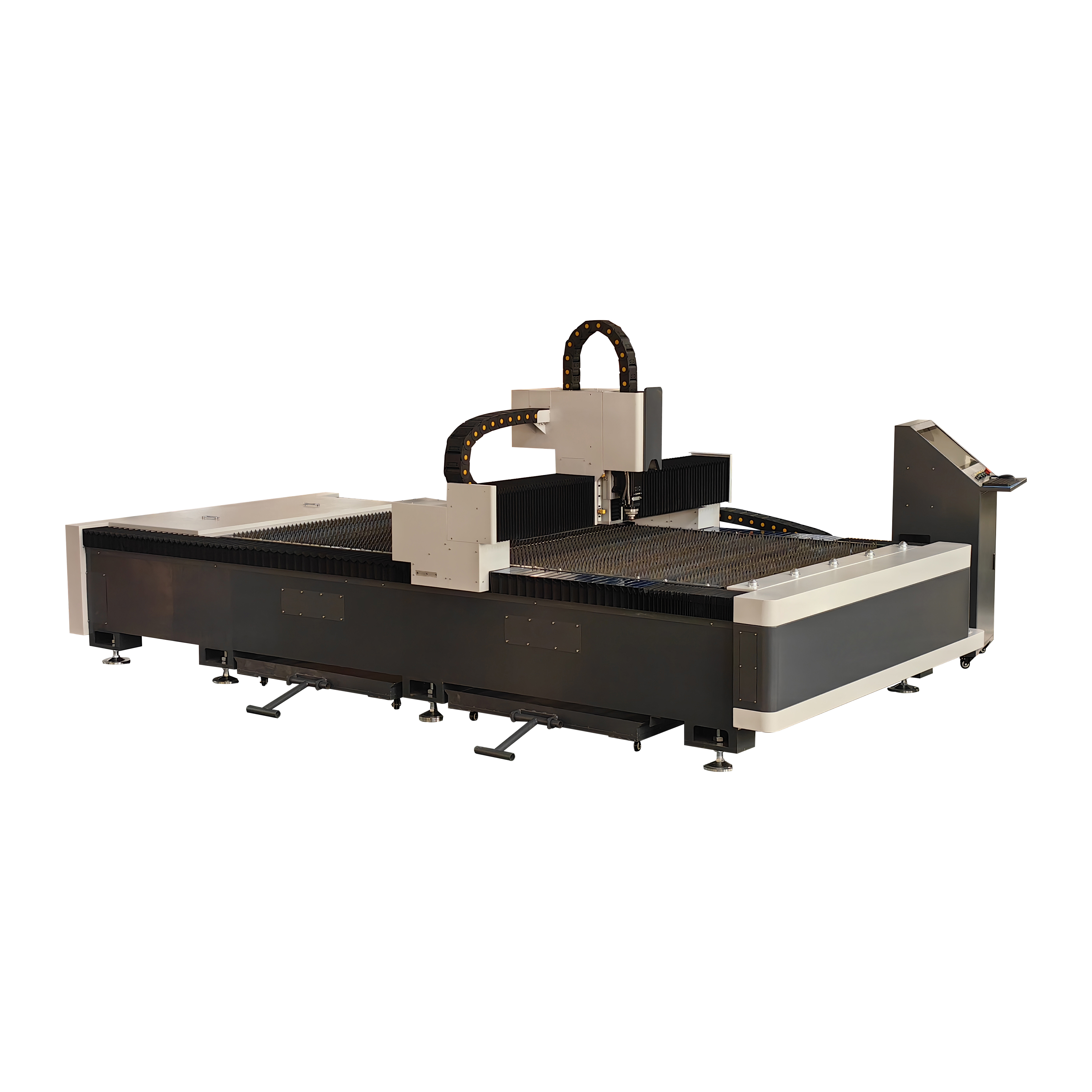
Flatbed sheet metal cutting relies on specific 2D vector formats. You must assess these formats for compatibility with your specific machine controller. DXF is the undisputed universal standard for 2D laser cutting. Its open-source nature makes it compatible with virtually every CAD and CAM software on the market. DXF files store 2D geometry as mathematical coordinates. This allows the laser to follow precise paths regardless of scale.
Versioning issues frequently arise with DXF files. Modern CAD programs export in the latest DXF version by default. Older machine controllers often fail to read these newer files. Exporting your designs as older AutoCAD formats, such as R14 or 2000, ensures maximum compatibility across different generations of equipment.
DWG is a proprietary Autodesk format. Many engineering departments use it natively. While some advanced CAM software can import DWG files directly, it often requires conversion to DXF for third-party nesting software. Sticking to DXF eliminates translation errors between different software ecosystems.
Transitioning from signage or graphic design to industrial cutting introduces challenges with AI and SVG files. Graphic designers use these formats for visual layouts. They often contain splines, unjoined nodes, or scaling issues. A graphic file might look perfect on screen but will cause a CNC fiber laser cutter to stutter, stop, or cut incorrect dimensions. Always convert AI or SVG files to DXF. Verify the dimensional accuracy in a dedicated CAD program before sending the file to the nesting software.
File Format | Primary Use Case | Compatibility | Shop Floor Reliability |
|---|---|---|---|
DXF | Standard 2D part geometry | Universal across all CAM software | Excellent (if exported as R14/2000) |
DWG | Native AutoCAD drafting | High within Autodesk ecosystem | Good (often requires conversion) |
SVG / AI | Graphic design and signage | Poor for industrial controllers | Low (requires heavy cleanup) |
STEP / IGES | 3D models and tube cutting | Requires specialized 3D CAM | Excellent for multi-axis machines |
Fabrication shops utilizing rotary attachments, dedicated tube cutting lasers, or 5-axis machines require 3D file formats. Standard 2D DXF files cannot convey the complex intersections, bevels, and multi-plane geometries required for these applications. STEP and IGES serve as the standard neutral 3D CAD formats in the manufacturing industry.
Specialized tube-cutting CAM software, such as TubesT, imports STEP files directly. The software analyzes the 3D model to recognize the specific profile. It identifies whether the material is square tubing, round pipe, or C-channel. The software then calculates the necessary laser head angles and rotary chuck movements to execute complex intersecting cuts, such as fishmouth joints for pipe welding.
Sheet metal unfolding is another critical 3D workflow. Engineers design electrical enclosures, brackets, and chassis as 3D folded models. Before the laser can cut the flat blank, the CAD software must unfold the 3D model into a 2D DXF file. This process requires precise calculation of the K-factor.
The K-factor represents the behavior of the specific metal during bending. When metal bends, the inside radius compresses and the outside radius stretches. The neutral axis remains unchanged. The K-factor dictates exactly how much the flat pattern must be adjusted to ensure the final folded part meets the required dimensional tolerances. Failing to apply the correct K-factor during the 3D-to-2D unfolding process results in flat parts that cut perfectly but bend to the wrong final size.
The machine controller does not read DXF or STEP files directly. It reads machine instructions. G-code is the alphanumeric language that controls the machine's servo motors, laser source, and assist gas valves. Understanding basic G-code commands helps operators troubleshoot cutting issues directly at the control panel.
A standard G-code file consists of sequential lines of commands. G00 commands rapid positioning. The laser head moves to a specific coordinate at maximum speed without firing the beam. G01 commands linear cutting. The laser fires and moves at a specified feed rate. G02 and G03 command clockwise and counter-clockwise circular interpolation for cutting holes and arcs. M-codes handle hardware functions. M03 might turn the laser on, while M05 turns it off. Other M-codes control the flow of oxygen or nitrogen assist gas.
Modern integrated control systems frequently use proprietary project files instead of raw G-code. CypCut, a dominant controller in the fiber laser market, uses the .LXD format. These proprietary files save the entire project state. They contain the nested geometry, the assigned toolpaths, the lead-in locations, and the specific material cutting parameters. This allows the operator to load a single file and immediately begin cutting without manually configuring gas pressures or focal lengths.
Proprietary files offer seamless machine integration. They reduce setup time on the shop floor. However, they lock the user into a specific software ecosystem. You cannot take an .LXD file and run it on a machine equipped with a different brand of controller. You must maintain the original DXF files to ensure you can generate new machine files if you switch equipment brands.
Poor file preparation causes machine crashes, severe edge burrs, and scrapped material. You must establish strict CAD guidelines to ensure precision CNC laser cutting. The most common error is leaving splines in the DXF file. Splines are complex mathematical curves. CNC controllers process lines and arcs efficiently but struggle to calculate spline trajectories in real-time. This causes the laser head to stutter, resulting in jagged edges and excessive heat input. You must convert all splines to polylines before exporting the file.
Open contours represent another major failure point. Every cut path must be a closed loop. If a node is left unjoined by even a fraction of a millimeter, the CAM software will not recognize it as a cuttable part. The laser will stop before completing the perimeter, leaving the part physically attached to the scrap skeleton.
Overlapping lines destroy cut quality. If a designer accidentally copies and pastes a line on top of itself, the laser will cut that exact path twice. The first pass cuts the metal. The second pass dumps massive amounts of heat into the already severed edge. This causes micro-welding, severe warping, and potential damage to the laser nozzle due to molten blowback.
Layer management dictates machine operations. You must use CAD layers or specific colors to separate different processes. Assign one color for the primary outer contour. Assign a second color for inner hole cutouts. Assign a third color for low-power surface engraving, such as part numbers or bend alignment marks. The CAM software reads these layers and applies the correct laser power and speed to each.
Kerf compensation is mandatory for accurate parts. The laser beam has a physical width. As it cuts, it vaporizes a small amount of material, known as the kerf. If the laser travels exactly on the drawn CAD line, the final part will be slightly undersized. CAM software applies kerf compensation by offsetting the toolpath to the outside of the part boundary by half the beam width.
Micro-joints, or tabbing, prevent machine crashes during batch processing. When cutting small parts, the high-pressure assist gas can blow the severed part out of the sheet. The part can tip vertically. If the laser head travels over a tipped part at rapid traverse speeds, it will cause a catastrophic nozzle collision. Placing tiny gaps in the cut path keeps the small parts attached to the main sheet. The operator manually snaps them out after the sheet is removed from the machine.
Your choice of CAM software heavily impacts your daily production throughput. Machine manufacturers typically include their own OEM software. These included packages handle basic importing, nesting, and parameter assignment. They work well for low-volume, high-mix job shops.
High-production environments require enterprise third-party solutions. Advanced software automatically imports massive batches of DXF or STEP files directly from an ERP system. The software reads the metadata attached to each file, identifying the required material type, thickness, and order quantity. It then automatically nests hundreds of parts across multiple sheets to maximize material yield and minimize scrap.
Material-specific file profiles dictate the actual cutting physics. The CAM software must adapt the file parameters based on the metal. Cutting 10mm carbon steel requires oxygen assist gas, a slow feed rate, and a specific focal position. Cutting 2mm aluminum requires high-pressure nitrogen, rapid feed rates, and different piercing parameters. Reflective metals like copper and brass demand specialized piercing frequencies to prevent back-reflection from damaging the laser source. Your software must allow you to save and instantly recall these material profiles to apply them to incoming CAD files.
Audit your current CAD export settings to ensure all files are saved as R14/2000 DXF formats with splines converted to polylines.
Establish a standardized color-mapping guide for your engineering team to separate cutting, piercing, and engraving layers.
Implement a mandatory pre-nesting checklist to verify all contours are closed and duplicate lines are deleted.
Request physical test cuts from machine vendors using your most complex, spline-heavy files to verify their controller's processing capabilities.
A: While some CAM software can import vector PDFs, it is highly unreliable for dimensional accuracy. PDFs frequently alter scale during export. You should always convert PDFs to DXF format and manually verify the critical dimensions before processing to avoid scrapping material.
A: Overlapping lines cause the laser to cut the exact same path multiple times. This results in excessive heat buildup, severe warping of the material, and potential micro-welding of the cut edges. It also increases the risk of molten metal blowing back into the nozzle.
A: CNC controllers process standard lines and arcs efficiently. They struggle to calculate the complex mathematical curves of splines in real-time. Converting splines to polylines ensures smooth, uninterrupted machine movement, preventing jagged edges and machine stuttering.
A: Micro-joints keep small parts physically attached to the main sheet during the cutting process. This prevents the high-pressure assist gas from tipping the parts vertically, which would cause a catastrophic collision with the rapidly moving laser head.
A: Kerf is the physical width of the material vaporized by the laser beam. CAM software applies kerf compensation by slightly offsetting the cutting toolpath to the outside of the part boundary. This ensures the final physical part matches the original CAD dimensions exactly.


