
Views: 0 Author: Site Editor Publish Time: 2026-09-16 Origin: Site


The industrial shift toward extreme miniaturization in medical devices, aerospace, and microelectronics requires permanent, high-contrast Direct Part Marking (DPM) on increasingly fragile substrates. Manufacturers face strict traceability mandates requiring the application of microscopic data matrices and serial numbers on components that cannot withstand traditional processing. Standard thermal marking systems and contact-based methods cause micro-cracking, melting, burning, or mechanical deformation on sensitive plastics, glass, and thin foils. This thermal damage leads to high scrap rates and compromised structural integrity in critical parts.
A 355nm UV Laser Marking Machine serves as the definitive solution for non-destructive, high-resolution marking. It fundamentally shifts the material interaction mechanism from thermal melting to photolytic bond breaking. You achieve permanent, high-contrast marks without compromising the physical integrity of delicate components, ensuring compliance with industry standards while maintaining product quality.
Understanding laser material interaction requires examining specific wavelengths and their corresponding photon energy. Standard industrial lasers operate in the infrared spectrum, typically around 1064nm. These systems rely entirely on photothermal processes. Infrared photons transfer energy by vibrating target molecules, which generates intense localized heat. This heat melts or vaporizes the surface to create a visible mark. While this thermal approach works exceptionally well for heavy metals like steel and aluminum, it fails completely on heat-sensitive polymers, thin films, and fragile substrates.
Ultraviolet lasers operate at a much shorter 355nm wavelength. This shorter wavelength carries significantly higher photon energy, measuring approximately 3.49 electron volts (eV). When these high-energy photons strike a surface, they trigger a photolytic reaction rather than a thermal one. The photons possess enough raw energy to directly break the chemical bonds holding the material together, such as carbon-carbon or carbon-hydrogen bonds in plastics. This process is widely known as cold laser marking. It alters the molecular structure without generating excessive heat, resulting in a chemical color change rather than a physical melt.
This fundamental difference in physics dictates application success on the factory floor. Photolytic marking allows you to process highly sensitive materials that would otherwise be destroyed by infrared heat. You can mark thin polyimide films, medical-grade silicones, and bare semiconductor wafers with absolute precision. The surrounding material remains completely unaffected by the beam. You achieve a permanent, high-contrast mark through molecular alteration, ensuring the substrate retains its original mechanical properties and structural integrity.
The Heat-Affected Zone (HAZ) is the primary enemy of micro-manufacturing and precision engineering. When a traditional laser melts a surface, the surrounding area absorbs residual heat. This heat causes the material to expand and contract rapidly during the cooling phase. In plastics, this thermal cycling leads to warping, foaming, and soot formation. In brittle materials like glass and ceramics, it causes micro-fractures. These invisible cracks severely degrade the structural integrity of the component, leading to premature failure in the field.
Operating a UV laser eliminates the HAZ almost entirely. The photolytic process occurs so rapidly that heat simply cannot transfer to adjacent areas. You mark the part without thermal degradation, keeping the material stable. Furthermore, laser marking is a completely non-contact process. You never apply physical force, clamping pressure, or mechanical drag to the component. This is an absolute requirement for thin-walled parts, flexible circuits, and fragile assemblies that would deform under the pressure of a dot peen or rotary engraving tool.
Preventing mechanical stress ensures high yield rates in production. You can mark medical catheters without altering their flexibility or introducing weak points in the tubing. You can mark aerospace fasteners without introducing stress risers that could lead to fatigue cracking. The absence of HAZ guarantees that the final product meets strict engineering tolerances. Your scrap rates drop significantly when you remove thermal and mechanical variables from the marking process, allowing for consistent, repeatable manufacturing.
Modern manufacturing demands absolute traceability from the component level up to the final assembly. Regulatory bodies require permanent identification on ultra-small components to track origin, manufacturing date, and batch data. Medical devices must carry Unique Device Identification (UDI) codes to comply with FDA regulations. Defense components require Unique Identification (UID) marks. Automotive parts need machine-readable datamatrices for strict supply chain tracking. These codes must often fit on microscopic surface areas, sometimes smaller than a single square millimeter.
Establishing baseline requirements for precision component marking starts with contrast and resolution. A 2D code is useless if a vision system or handheld scanner cannot read it. The mark must exhibit sharp edges and high contrast against the background material. UV lasers excel in this specific metric. They produce crisp, dark marks on light materials and highly visible white marks on dark materials. The ultra-fine beam allows you to condense massive amounts of data into a tiny footprint, maintaining the strict module size requirements for DataMatrix ECC200 standards.
You must also evaluate the durability of the mark under harsh conditions. Printed labels degrade, peel, or fade over time. Inkjet marks wash off during chemical sterilization or mechanical scrubbing. Direct Part Marking with a UV laser permanently alters the substrate itself. The traceability data survives chemical washes, high-temperature autoclaving, and prolonged environmental exposure. This permanence is non-negotiable for critical components like pacemakers, surgical instruments, or aerospace turbine blades that operate in extreme environments.
Functional traceability is only half the requirement for modern products. You must also maintain the aesthetic quality and tactile feel of the component. Consumer electronics, premium medical devices, and high-end automotive interiors require flawless branding. The primary rule for processing these parts is "no burning, no damage." Thermal lasers often leave raised edges, slag, or charred residues. This ruins the tactile feel, creates potential contamination points, and destroys the visual appeal of the component.
UV lasers achieve perfect aesthetic consistency across production batches. They induce a photochemical reaction that changes the color of the plastic without foaming or charring the surface. You get a smooth, flush finish that cannot be felt by running a finger over the mark. The tactile integrity of the part remains identical to its pre-marked state. This is vital for components that come into contact with human tissue, where raised edges could harbor bacteria, or for parts that require precise aerodynamic profiles.
You can produce crisp, high-contrast corporate logos alongside functional data in a single cycle. The beam precision allows for intricate graphics, fine typography, and complex geometric patterns. You maintain premium product aesthetics while meeting strict regulatory requirements. The ability to combine branding and traceability in a single, non-destructive operation streamlines the manufacturing workflow and eliminates the need for secondary printing processes.
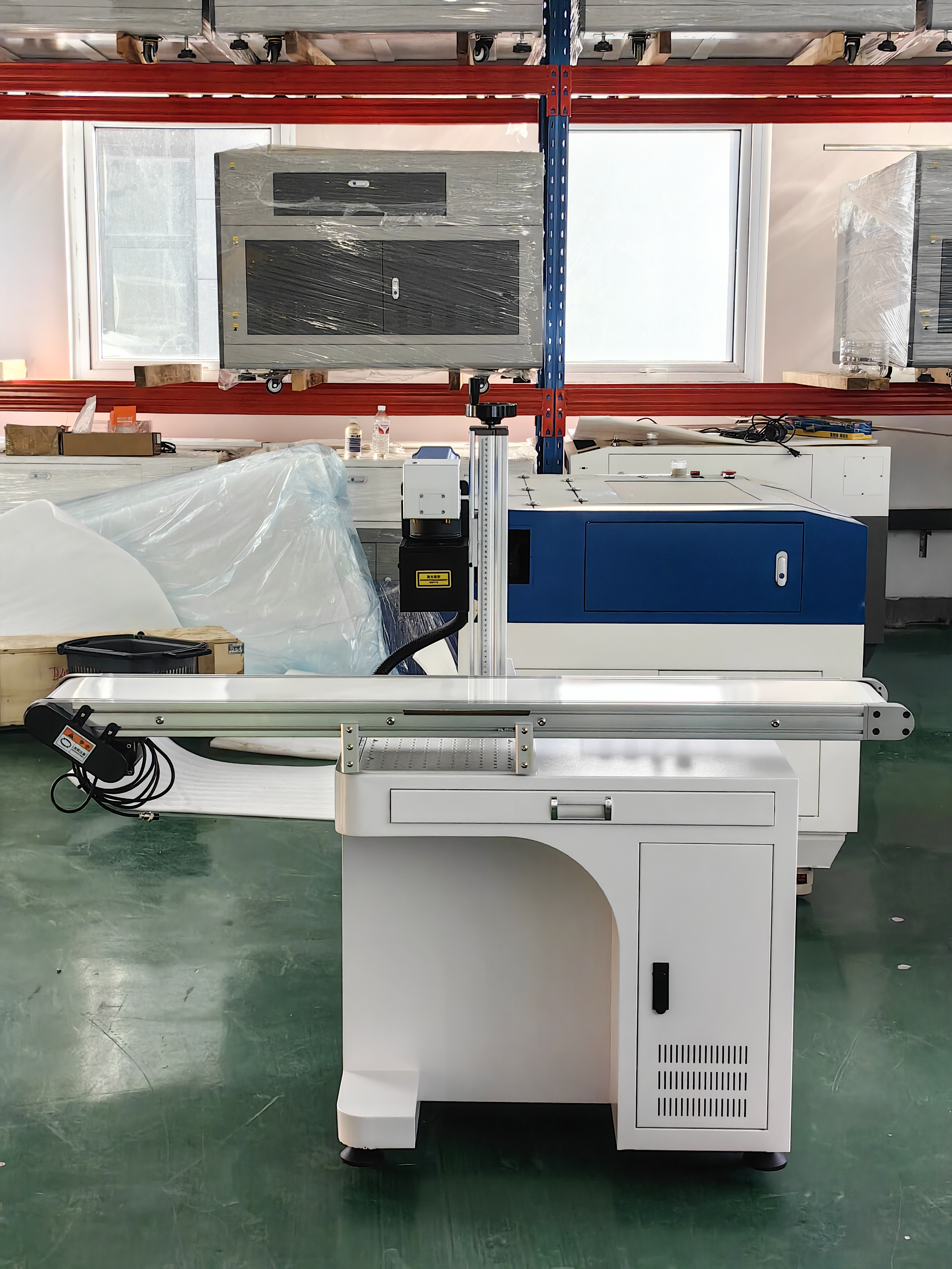
Choosing the right laser wavelength dictates your production success and directly impacts your scrap rates. Fiber lasers operate at 1064nm and are the undisputed workhorses of the metalworking industry. They excel at deep engraving on steel, aluminum, and titanium. However, their reliance on intense heat makes them entirely unsuitable for sensitive applications. If you point a fiber laser at a clear plastic part, the beam will either pass straight through without leaving a mark or melt the surface into an unrecognizable, charred mass.
You must specify a UV laser marking machine when thermal damage is unacceptable. Thin polymers, flexible foils, and transparent plastics require the 355nm wavelength. The high photon absorption rate of UV light ensures the energy stays exactly where you focus it. The material absorbs the UV energy immediately at the surface level, triggering the color change before heat can build up and spread through the substrate.
Consider a medical tube made of thin PTFE or silicone. A fiber laser will easily puncture the tube wall, rendering the part useless. A UV laser will create a dark, readable mark on the surface without compromising the wall thickness or flexibility. Whenever you process materials that are prone to melting, burning, or micro-cracking, UV technology is mandatory. It provides a safety margin and processing window that infrared lasers simply cannot match.
Green lasers operate at 532nm, sitting directly between UV and Fiber lasers in the electromagnetic spectrum. Green lasers are excellent for marking highly reflective metals like copper, gold, and silver, which typically reflect 1064nm infrared light. They also process certain plastics very well. The 532nm wavelength provides better absorption than 1064nm, reducing the thermal footprint. However, Green lasers still rely partially on photothermal reactions, meaning they generate more heat than a UV system.
While Green lasers handle some sensitive tasks, UV remains superior for highly transparent materials. Glass, sapphire, and clear polymers absorb 355nm light much more efficiently than 532nm light. If you need to mark a clear glass syringe, a transparent polycarbonate lens, or a microfluidic device, a UV system is the only reliable choice. The UV wavelength guarantees a high-contrast mark without micro-fracturing the fragile substrate or passing through the material entirely.
Furthermore, UV lasers achieve the absolute smallest spot sizes available in industrial marking. The laws of optics dictate that the shorter the wavelength, the tighter you can focus the beam. A 355nm beam focuses to a much smaller point than a 532nm beam using the same optics. This makes UV the undisputed leader for micro-machining, semiconductor processing, and ultra-high-density data marking on microscopic components.
| Laser Type | Wavelength | Primary Mechanism | Best Suited Materials | Spot Size Capability |
|---|---|---|---|---|
| Fiber Laser | 1064nm (Infrared) | Photothermal (Heating/Melting) | Metals, hard opaque plastics | Medium (Good for standard text) |
| Green Laser | 532nm (Visible Green) | Hybrid (Thermal/Photochemical) | Reflective metals (Copper/Gold), some plastics | Small (Good for detailed graphics) |
| UV Laser | 355nm (Ultraviolet) | Photolytic (Cold marking/Bond breaking) | Glass, clear plastics, ceramics, thin foils | Ultra-Fine (Best for micro-codes) |
When evaluating a laser system for precision applications, beam quality is a critical metric. It is measured by the M⊃2; factor. A perfect Gaussian beam has an M⊃2; value of exactly 1.0. High-end UV lasers typically feature an M⊃2; value of less than 1.2. This near-perfect beam quality allows the focusing optics to concentrate the laser into an incredibly tight spot. With the right lens configuration, you can achieve spot sizes down to 10 micrometers.
This microscopic spot size correlates directly to your marking capabilities on the production floor. A smaller spot size concentrates the photon energy into a tighter area, increasing the energy density without increasing the overall wattage. This allows you to mark high-density data on severely limited surface areas. You can engrave a 20-character serial number on the edge of a printed circuit board or place a readable QR code on the head of a surgical screw.
Poor beam quality results in a blurry, diffused spot. This causes the mark to look fuzzy, reduces the readability of barcodes, and bleeds heat into the surrounding material. When processing miniature components, you cannot compromise on beam quality. The M⊃2; value dictates the sharpness, contrast, and ultimate success of your traceability program. Always verify the M⊃2; specification before integrating a laser into a micro-manufacturing line.
UV lasers come in various power configurations, typically ranging from 3W up to 15W or more. You must match the wattage directly to your specific application. More power does not always equal better results. In cold marking, applying too much power can overwhelm the photolytic process, introduce unwanted heat, and damage the substrate. You need a strict framework for selecting the correct output.
Lower power systems, specifically 3W to 5W models, are highly effective for slow, ultra-delicate plastic marking. If you are marking thin medical films, sensitive electronic casings, or flexible printed circuits, 3W provides perfect control. It alters the surface gently without any risk of penetration or thermal distortion. These lower-wattage systems are ideal for standalone workstations where cycle time is secondary to absolute precision.
Higher power systems, such as 10W, 15W, and above, are required for entirely different scenarios. You need higher wattage for deep engraving on tough materials like glass, sapphire, or ceramics. High power is also mandatory for high-speed line integration. If parts are moving rapidly down a conveyor or wire is being extruded at 100 meters per minute, the laser has only milliseconds to complete the mark. A 15W system delivers the necessary photon density instantly, ensuring a dark, readable mark at high line speeds.
Modern production environments require seamless equipment integration. A standalone laser is insufficient for high-volume manufacturing. You must evaluate the system's I/O connectivity and communication protocols. The laser controller must communicate flawlessly with the main assembly line Programmable Logic Controller (PLC). Look for native support for industrial protocols like PROFINET, Ethernet/IP, or Modbus TCP to ensure reliable handshakes and trigger signals.
Software capabilities are equally important for automated lines. The marking software must handle dynamic data injection seamlessly. As parts move down the line, the system must automatically pull unique serial numbers, timestamps, and batch codes from a central database or ERP system. The software should format this data instantly into a 2D matrix and execute the mark without operator intervention. This eliminates human error in the traceability chain and prevents duplicate serial numbers.
Physical integration requires addressing focal tolerance. Laser marking relies on keeping the target surface exactly at the focal point of the lens. If part heights vary on your production line, the mark will blur and fail. Integrating a 3D autofocus system solves this issue. The system uses a displacement sensor to measure the exact height of each incoming part. It dynamically adjusts the internal optics to keep the beam perfectly focused, regardless of surface variations or fixturing inconsistencies.
Direct Part Marking is governed by the strict laws of optics. The most critical physical constraint is laser focal depth, often referred to as the Rayleigh length. The laser beam is only in perfect focus within a very narrow vertical window. If the surface of your component moves outside this window, the beam expands. The energy density drops immediately, the photolytic reaction stops, and the mark fails to appear.
Laser marking is optimal for flat surfaces. When you mark flat components, the entire marking area remains within the focal depth. However, marking round or curved parts introduces significant complexity. If you attempt to mark a cylinder with a standard fixed lens, the center of the mark will be sharp, but the edges will stretch, fade, and distort as the surface curves away from the focal point.
To mark parts with a radius of curvature greater than 4 inches, you need specialized hardware. You can integrate a rotary axis. The rotary indexer turns the part synchronously with the laser, keeping the active marking area perfectly flat relative to the beam at all times. Alternatively, you can use a 3D dynamic focusing lens. This technology rapidly shifts the focal point in real-time along the Z-axis, allowing the beam to "wrap" around curved geometries without distortion or loss of energy density.
Implementing advanced laser technology requires understanding its specific maintenance profile. UV laser diodes and internal crystals have a different lifespan compared to standard fiber lasers. A high-quality fiber laser source might run for 100,000 hours with zero maintenance. A UV laser typically has a realistic lifespan of around 20,000 hours before requiring service. The internal LBO crystals used for Third Harmonic Generation (THG) degrade over time and require periodic shifting to expose fresh crystal material to the beam.
You must plan for this maintenance cycle in your production schedule. The 20,000-hour mark usually requires a diode replacement or a factory refurbishment. To maximize this lifespan and stretch the time between service intervals, you must strictly control the operating environment. UV optics are highly sensitive to contamination. Dust, oil vapors, and humidity will degrade the internal crystals rapidly, causing power drops and beam distortion.
You must install UV systems in clean, climate-controlled environments. Maintain stable ambient temperatures and low humidity. If you must deploy the machine on a harsh factory floor, you need an IP-rated enclosure. The enclosure must feature active cooling and positive air pressure to keep airborne contaminants away from the laser head. Proper environmental control directly extends the life of your equipment and ensures consistent marking performance.
Laser safety is a paramount concern on the factory floor. A 355nm beam is completely invisible to the human eye and can cause severe, irreversible retinal damage in a fraction of a second. You must adhere to strict safety compliance standards. Unenclosed lasers operate as Class 4 devices. They require dedicated laser safe rooms, interlocked doors, warning lights, and mandatory safety eyewear with the correct Optical Density (OD) rating for all personnel in the vicinity.
The best practice for manufacturing lines is to utilize a Class 1 safety enclosure. A Class 1 enclosure completely contains the laser beam during operation. It features laser-safe viewing windows specifically rated to block 355nm wavelengths. The enclosure incorporates dual-channel safety interlocks that instantly shut down the laser if the door opens. This allows you to deploy the machine safely in open production areas without requiring specialized protective gear for the operators.
Furthermore, you must implement proper fume extraction. Even though UV technology utilizes cold laser marking, the photolytic process still vaporizes microscopic amounts of material. This creates airborne particulate matter and volatile organic compounds (VOCs). You must connect a dedicated fume extractor to the marking enclosure. The extractor pulls the hazardous vapors through HEPA and activated carbon filters, ensuring operator safety and maintaining a clean optical path for the laser beam.
A UV laser marking machine stands as the non-negotiable standard for modern precision manufacturing. When thermal damage is unacceptable, non-contact processing is required, and micro-precision is critical, 355nm technology delivers. It provides permanent, high-contrast traceability on the most fragile substrates without compromising structural integrity or aesthetic quality.
When shortlisting equipment, prioritize vendors based on specific technical merits rather than generic specifications. Evaluate their beam quality (M⊃2; values) and available power configurations to ensure they match your exact material requirements. Scrutinize their software integration capabilities for automated lines. Most importantly, ensure the vendor provides an application testing lab to verify material compatibility before you finalize any purchase.
A: The primary difference is the wavelength and the marking mechanism. Fiber lasers operate at 1064nm and use intense heat to melt materials. UV lasers operate at 355nm and utilize cold photolytic marking. The UV photons break molecular bonds directly. This prevents thermal damage, warping, and micro-cracking on sensitive parts.
A: UV lasers excel at marking highly sensitive materials. This includes clear plastics, polycarbonate, glass, ceramics, silicon wafers, and thin metal foils. Because of the high absorption rate of the 355nm wavelength, they produce high-contrast, permanent marks on these substrates without burning or melting the surface.
A: Cold laser marking is a non-contact process that uses high-energy ultraviolet light to break chemical bonds at the molecular level. Unlike infrared lasers that generate intense localized heat, this photolytic process alters the material surface without creating a Heat-Affected Zone (HAZ). It prevents burning, warping, or structural damage.
A: Yes, but it requires specific hardware. Laser marking is highly sensitive to focal depth. If a part has a radius of curvature greater than 4 inches, the beam will lose focus on the edges. You must use a rotary indexer to turn the part or a 3D dynamic focusing system to adjust the focal length in real-time.
A: A high-quality UV laser diode typically lasts around 20,000 hours. This lifespan depends heavily on the operating environment and power levels. While this is shorter than the lifespan of a fiber laser, the replacement cycle is justified by the system's unique ability to process ultra-sensitive precision components without damage.


