
Please Choose Your Language
Views: 0 Author: Site Editor Publish Time: 2026-08-16 Origin: Site


Modern structural design demands complex intersecting joints, precise bevels, and custom geometric slots to meet rigorous engineering standards. Traditional mechanical processing methods, such as manual sawing, milling, and drilling, introduce severe production bottlenecks on the shop floor. These outdated mechanical methods suffer from tolerance stacking errors, require excessive manual handling between different workstations, and drive up labor costs when processing complex tube profiles. Fabricating a simple saddle joint or a fish-mouth cut mechanically often requires multiple setups, custom fixtures, and extensive deburring, which destroys production efficiency.
A modern Tube Metal Laser Cutting Machine directly resolves these bottlenecks by consolidating multiple operations into a single automated cycle. By utilizing synchronized kinematic motion, advanced workholding, and highly precise thermal control, this technology transforms raw stock into finished, weld-ready components in one setup. Understanding how these systems execute intricate toolpaths provides a solid framework for evaluating equipment for in-house adoption and long-term process reliability.
Kinematic Synchronization: Complex profile processing relies on the simultaneous, computer-controlled movement of the laser cutting head and the rotational axis of the tube to translate a design file into accurate cuts.
Power Threshold Realities: Unlike flatbed lasers, a tube laser cutting machine typically caps power (often around 5 kW) to prevent the beam from penetrating and damaging the opposite inner wall of the tube.
Process Consolidation: Adopting a dedicated pipe laser cutter eliminates secondary operations by combining cutting, drilling, and weld-prep beveling into a single automated cycle.
Software Dependency: The accuracy of complex geometries is heavily dependent on the machine’s CAM software translating 3D CAD models into optimized, collision-free toolpaths.
Intelligent Material Handling: High-end systems utilize optical or tactile sensors for weld seam detection and twist compensation, ensuring structural integrity and batch-to-batch repeatability.
To evaluate a machine's capability, buyers must first understand the mechanical requirements for maintaining tight tolerances on non-flat surfaces. Processing cylindrical, square, or asymmetrical stock introduces dynamic variables completely absent in flat sheet cutting. The machine must constantly adjust to the curvature and rotation of the material while maintaining a perfect focal distance. If the focal point shifts by even a fraction of a millimeter, the cut quality degrades instantly, leaving heavy dross or causing the beam to lose its piercing capability.
Executing complex geometries requires seamless interplay between linear and rotational axes. The standard linear axes position the cutting head in three-dimensional space above the material. Simultaneously, the rotational axes turn and advance the raw stock through the cutting zone. Continuous interpolation algorithms within the CNC controller synchronize these movements at millisecond intervals.
This synchronization allows the laser head to maintain a perpendicular or precisely angled focal point as the tube rotates. Maintaining this optimal focal distance ensures process reliability and clean edge quality across complex geometries. High-performance servo motors and absolute encoders are mandatory to achieve the rapid acceleration and deceleration required for intricate slotting and hole-cutting on curved surfaces. When cutting a square tube, for example, the rotational axis must accelerate rapidly across the flat side and decelerate sharply at the corner to allow the laser head to track the radius without losing position.
Material deflection during high-speed rotation ruins dimensional accuracy. Pneumatic and servo-driven chucks secure the raw material, applying consistent clamping force without crushing thin-walled stock. Servo-driven chucks offer superior control, automatically adjusting clamping pressure based on the material's wall thickness and profile type. Self-centering mechanisms are required for asymmetrical or custom-shaped tubing, ensuring the material's true geometric center aligns perfectly with the machine's rotational axis.
Long tube lengths, often starting as 24-foot raw bundles, introduce the physical challenge of whip. Whip occurs when the unsupported center of the tube bows outward during rapid rotation, causing massive vibrations at the cutting head. Automated steady rests deploy along the machine bed to support the material. These programmable supports retract dynamically as the chuck and cutting head pass, preventing vibration without interrupting the cutting cycle.
Furthermore, raw structural tubing features a longitudinal weld seam created during the tube manufacturing process. This seam affects downstream bending operations and aesthetic alignment. High-end systems integrate optical cameras or tactile sensors for automated weld seam detection. The machine identifies the seam and rotates the stock to a programmed orientation before the first cut begins, ensuring the seam is hidden or placed on the neutral axis for subsequent rotary draw bending.
The physics of tube cutting dictate that higher wattage is not always better. A high-power beam easily pierces the top wall but carries the severe risk of opposite-side blow-through. If the beam strikes the inner back wall, it causes metallurgical damage, slag buildup, or complete penetration. Therefore, a tube laser cutting machine is often optimized at or below 5 kW. This power cap ensures the beam cuts the top surface cleanly but diffuses before damaging the internal cavity.
Active cooling and precise assist gas flow dynamics control the heat-affected zone. Nitrogen provides a clean, oxide-free cut on stainless steel by shielding the molten pool from ambient oxygen. Conversely, oxygen facilitates an exothermic reaction, adding thermal energy to cut through thicker mild steel efficiently. To protect internal surface finishes for fluid-carrying or architectural applications, operators utilize internal spatter guards or mandrel extraction systems. These physical barriers are inserted into the tube cavity to catch molten slag and deflect the beam before it adheres to the opposite inner wall.
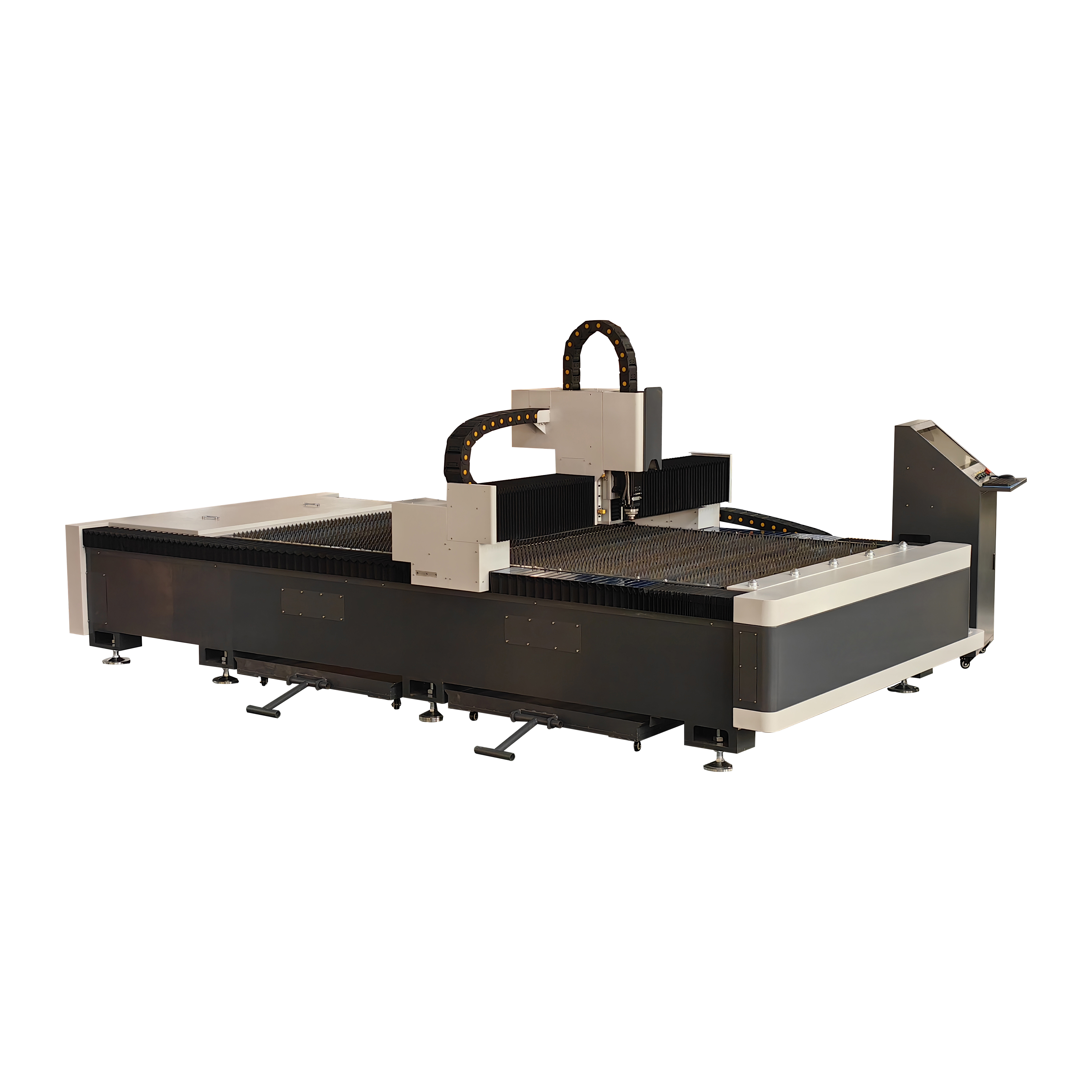
Mapping machine features to specific production outcomes requires a clear evaluation framework. Buyers must assess geometric requirements and material versatility across mild steel, stainless steel, and aluminum alloys to ensure the equipment meets daily production demands without requiring constant manual intervention. Effective metal tube fabrication relies on matching the machine's mechanical limits to the shop's heaviest and most complex workloads.
Producing chamfers and bevels directly on the machine requires a specialized 5-axis cutting head. This articulating head tilts up to 45 degrees to create angled cuts, such as V, Y, or K bevels, along the material edge. Beveling directly impacts downstream welding efficiency. Welders receive parts with precise joint fit-up, completely eliminating manual grinding and edge preparation on the shop floor.
This tight fit-up ensures deeper weld penetration and superior structural joint integrity. When fabricating heavy load-bearing frames, the ability to cut a perfect 45-degree weld prep on a thick-walled structural tube saves hours of manual labor per assembly. The 5-axis head must utilize capacitive height sensing to maintain the exact stand-off distance even as the head tilts, compensating for any minor surface irregularities on the raw stock.
Modern processing extends far beyond standard round and square tubes. Advanced machines slice through open profiles like C-channels, L-angles, elliptical extrusions, and custom architectural shapes. Processing these open profiles requires specialized chuck jaws and sophisticated software algorithms that prevent the laser from firing into empty space.
Processing raw stock often reveals material bowing or twisting, as structural steel is rarely perfectly straight from the mill. Sensor technology maps the actual physical dimensions of the loaded profile before cutting begins. The control system then automatically compensates the toolpath in real-time, adjusting for these physical deviations. If a 20-foot tube has a slight twist, the machine rotates the chucks dynamically to keep the cutting head perfectly aligned with the intended geometry, maintaining strict dimensional accuracy across the entire length.
Profile Type | Typical Applications | Workholding Challenge | Software Compensation Required |
|---|---|---|---|
Round Tube | Handrails, fluid piping, roll cages | Preventing crushing on thin walls | Basic rotary interpolation |
Square / Rectangular HSS | Structural frames, equipment bases | Maintaining focal distance at corners | Corner acceleration/deceleration mapping |
C-Channel / Angle Iron | Trailer frames, structural supports | Asymmetrical clamping and balance | Open-profile beam suppression |
Custom Extrusions | Architectural facades, aerospace parts | Custom jaw design and alignment | Full 3D surface mapping and twist compensation |
The translation process from a 3D design to executable machine code must be highly reliable. Operators rely on specialized CAM software to shape metal tubes and profiles without manual G-code editing. Critical software features dictate machine efficiency and material utilization. Automatic nesting algorithms analyze the production schedule and arrange parts along the raw stock for high material yield, minimizing scrap skeletons.
Collision detection simulates the entire cutting cycle virtually before the machine moves. This simulation prevents the cutting head from crashing into the chucks, the steady rests, or the material itself during complex 5-axis maneuvers. Kerf compensation automatically adjusts the toolpath for the exact width of the laser beam. This ensures that complex intersections, such as a tab-and-slot joint, fit together perfectly during assembly without requiring manual filing or forcing.
Analyzing the core laser generation technologies available in the market helps clarify which system aligns with specific fabrication requirements. While the industry has heavily shifted toward one technology, understanding the physics behind both ensures a well-informed capital equipment decision.
Fiber technology dominates modern processing facilities. The solid-state fiber optic delivery system generates a wavelength of 1.06 micrometers. This shorter wavelength boasts superior absorption in reflective metals like aluminum, brass, copper, and galvanized steel. This high absorption rate translates to distinct advantages in cutting speed for thin-to-medium wall thicknesses, often cutting three to five times faster than older technologies.
Furthermore, fiber systems operate with significantly lower maintenance costs. They lack the delicate internal mirrors, bellows, and continuous laser gas consumption required by older technologies. The beam is generated in active fibers and delivered directly to the cutting head via a flexible fiber optic cable, eliminating the need for complex optical alignment and routine mirror cleaning.
While fiber is the absolute standard for new installations, CO2 lasers still serve specific legacy use cases. Facilities processing exceptionally thick-walled mild steel or performing non-metallic cross-processing might still evaluate CO2 systems. The 10.6-micrometer wavelength provides a very smooth edge finish on thick mild steel plates.
However, for tube processing, the advantages of CO2 are rapidly diminishing. The physical constraints of delivering a CO2 beam via flying optics to a moving, rotating tube make the mechanical design of CO2 tube lasers inherently complex and prone to alignment issues. Fiber technology has largely rendered CO2 obsolete for dedicated structural profile cutting.
Selecting the right technology involves balancing the initial capital expenditure against long-term operating expenses and throughput gains. Fiber systems require a higher initial investment but deliver lower electrical consumption, zero laser gas costs, and vastly superior cutting speeds. The resulting throughput gains typically offset the higher upfront cost within the first few years of operation. Reduced maintenance downtime and the ability to process highly reflective materials without damaging the laser source make fiber the definitive choice for modern fabrication.
Identifying adoption hurdles before capital deployment prevents costly production delays. Integrating complex CNC machinery requires careful planning regarding personnel, facility layout, and ongoing maintenance protocols. A poorly planned installation can leave a high-end machine sitting idle while the facility scrambles to upgrade utilities or train staff.
Transitioning operators from 2D flatbed or manual cutting to 3D tube processing presents a steep learning curve. The spatial reasoning required to troubleshoot 5-axis motion and rotational interpolation is complex. Operators must understand how material twist affects the cut and how to adjust focal positions for varying wall thicknesses.
To mitigate this risk, buyers must negotiate comprehensive vendor-supplied training that includes both software programming and hands-on machine operation. Evaluating the intuitive nature of the Human-Machine Interface during the purchasing phase is critical. Modern interfaces utilize touchscreen controls and visual part representations, lowering the barrier to entry. Hiring strategies should target personnel with 3D spatial awareness, previous multi-axis CNC experience, or strong backgrounds in CAD/CAM programming.
Underestimating the physical footprint of the equipment leads to severe layout issues. These machines are exceptionally long, especially systems equipped with automated bundle loaders and finished part unloaders. Conducting a thorough floor plan analysis ensures adequate space for material flow, allowing forklifts to load 24-foot bundles safely.
To properly prepare a facility for installation, plant managers should follow these specific steps:
Map the exact footprint on the shop floor, including the bundle loader, outfeed table, and safety light curtain perimeters.
Verify electrical drop capacity for the main power supply, the industrial water chiller, and the dust collector.
Route high-pressure assist gas lines (Nitrogen and Oxygen) directly to the machine's internal regulators to prevent pressure drops during cutting.
Install spark-arresting dust collection ductwork to safely extract hazardous metallic fumes from the cutting enclosure.
Processing generates abrasive cutting dust, causing increased wear on rotational chucks and exposing delicate optics to contamination. The continuous rotation of heavy steel tubes puts immense strain on chuck jaws and servo motors. Implementing strict preventative maintenance schedules mitigates this mechanical wear.
Buyers should evaluate machines featuring fully sealed optical paths, which protect the cutting head lenses and protective cover glasses from environmental debris. Automated lubrication systems are essential. These systems ensure linear guides, ball screws, and rack-and-pinion drives receive consistent, metered greasing, reducing unexpected downtime and extending the lifespan of critical motion components.
Calculating the true return on investment requires analyzing value influencing factors beyond just the machine's hourly rate. The financial impact is realized through process consolidation, material savings, and increased production capacity.
Adopting a dedicated pipe laser cutter quantifies labor and time saved by eliminating separate sawing, drilling, milling, and deburring stations. Traditionally, a single structural component might move across four different machines, requiring four separate operators and accumulating queue time at each station.
With a laser system, a single operator loads raw stock and unloads a finished part ready for welding. This consolidation drastically reduces work-in-progress inventory, frees up valuable floor space previously occupied by drill presses and bandsaws, and shortens overall lead times from weeks to days.
Automated nesting software analyzes the production schedule and fits multiple parts onto a single length of raw stock. The software calculates the most efficient layout to minimize the remaining drop. Common-line cutting shares a single laser cut between two adjacent parts, eliminating the kerf waste between them and reducing total cutting time.
These software-driven strategies reduce raw material waste, maximizing the yield from every purchased bundle of steel. Over a fiscal year, increasing material yield by just a few percentage points translates to massive savings in raw steel procurement costs.
Evaluating the impact of automation dictates long-term scalability. Adding automated bundle loaders allows the machine to pull raw stock continuously without forklift intervention. The loader separates individual tubes from a bulk bundle, measures them, and feeds them into the chucks automatically.
Integrating robotic part sorting systems or automated drop tables enables lights-out or semi-autonomous operation. Finished parts are conveyed out of the machine enclosure and sorted into designated bins. This automation readiness allows fabrication shops to scale production volume and take on larger contracts without proportionally increasing headcount or running expensive weekend shifts.
A modern tube processing system is not just a faster saw; it is a comprehensive profiling center that redefines structural fabrication capabilities and process reliability. By consolidating multiple mechanical steps into one continuous thermal process, fabrication facilities eliminate tolerance stacking, drastically reduce labor dependencies, and achieve unprecedented geometric accuracy.
Base your equipment shortlist on your most complex geometric requirements, maximum wall thickness, and required daily throughput rather than just peak laser wattage.
Request a detailed time study from prospective machine vendors to compare theoretical laser cycle times against your current manual mechanical processes.
Demand a physical sample cut of your most difficult intersecting joint to verify the software's nesting efficiency and the machine's mechanical accuracy on real material.
Audit your facility's floor space and electrical infrastructure early to ensure complete compatibility with automated bundle loaders and high-capacity extraction systems.
A: Maximum wall thickness depends on the laser source wattage and material type. Standard 3 kW to 5 kW fiber systems easily process mild steel up to 12mm (0.5 inches) and stainless steel up to 8mm. Specialized high-power systems can push these limits further, but processing speed decreases significantly as thickness increases.
A: Power is capped to prevent the laser beam from penetrating the top wall and continuing through to damage the opposite inner wall. Unlike flat sheet cutting, the hollow nature of tubes requires precise thermal control to avoid blow-through, slag adhesion, or metallurgical damage to the back surface.
A: Yes, advanced machines handle open profiles. They utilize specialized chucks for asymmetric clamping and rely on capacitive height sensors to maintain focal distance. The software must also support open-profile toolpaths to prevent the cutting head from attempting to cut non-existent material in the open space.
A: The machine prevents opposite-side damage by optimizing laser wattage, adjusting focal depth, and utilizing precise cutting speeds. Operators also use internal spatter guards or copper mandrels inserted into the tube cavity to block the beam and catch molten slag during the initial piercing phase.
A: 2D cutting uses a fixed head that remains perpendicular to the material surface, suitable for straight cut-offs and standard holes. 3D bevel cutting utilizes a 5-axis articulating head that tilts to create angled chamfers and complex weld preps directly on the material edge.
A: High-end systems feature optical cameras or tactile sensors that scan the raw stock to detect the longitudinal weld seam. Once identified, the machine automatically rotates the tube to a programmed orientation, ensuring the seam is placed consistently for downstream bending or aesthetic purposes.
A: You design parts in standard 3D CAD software. However, you need specialized CAM software provided by the machine vendor to translate those 3D models into optimized toolpaths, handle nesting, apply kerf compensation, and generate the specific machine code required for multi-axis rotation.


