
Please Choose Your Language
Views: 0 Author: Site Editor Publish Time: 2026-07-20 Origin: Site


Scaling production by doubling the cutting heads on a Dual Head CO2 Laser Cutting Machine theoretically doubles throughput. It also squares the number of variables required to maintain cut quality. A common failure state in high output laser cutting occurs when one head cuts cleanly while the secondary head fails to penetrate. This mismatch results in wasted material, rejected batches, and lost time troubleshooting optical paths. We need a systematic framework for evaluating, calibrating, and maintaining a two head laser machine. Applying this framework ensures reliable performance and protects profit margins in high-volume production environments. Operators must move beyond basic operation and understand the mechanical and optical physics at play. You cannot simply press start and expect identical results across a wide gantry without rigorous baseline calibration. We will break down the exact steps to keep both heads firing perfectly.
Beam Path Integrity is Non-Negotiable: Consistent output across two heads requires absolute precision in mirror alignment and beam splitting/delivery; a 1mm deviation at the source multiplies exponentially at the focal point.
Matched Optics Prevent Spot Variations: Both heads must use matched focal lenses and nozzle diameters; mixing focal lengths or nozzle geometries destroys consistency.
Independent Focal Control is Critical: Variations in material thickness demand independent Z-axis adjustments for each head to maintain identical spot sizes and energy density.
Power Distribution Defines Architecture: Choosing between a single-tube beam-splitter setup and a dual-tube system dictates your maintenance overhead, power consistency, and failure risks.
Environmental and Material Baselines: Uneven materials, back-reflection risks, and inconsistent air assist pressure will defeat even perfectly aligned optics.
To achieve consistent cuts, operators must first understand how their specific machine distributes laser energy. A machine sends power to multiple heads using one of two primary architectures. Each design requires a different maintenance approach to keep the secondary head cutting reliably. You cannot treat a beam-splitter system the same way you treat a dual-tube system. The physics of power delivery change entirely based on the source configuration.
A single high-power CO2 tube generates the initial beam. The system uses a specialized optic to reflect 50% of the beam to head one. It passes the remaining 50% through to head two. This setup offers a lower initial cost. You only maintain a single laser tube and power supply. However, it remains highly susceptible to optic degradation. If the beam splitter degrades or accumulates dust, power distribution skews. A 50/50 split can quickly become a 60/40 split. This instantly destroys cut consistency across the bed. You will notice one side of your material cutting perfectly while the other side barely scores the surface. Maintaining this system requires absolute cleanliness. The half-mirror is the most sensitive component in the entire machine. Even a slight film of vaporized acrylic on this mirror will absorb laser energy, heat up, and eventually crack or warp, destroying your beam profile.
When operating a single-tube splitter system, you must also account for beam divergence. The beam traveling to the second head travels further than the beam traveling to the first head. As a laser beam travels through the air, it naturally expands. By the time the 50% passed beam reaches the secondary flying optic, its diameter is slightly larger than the reflected beam at the primary head. This means the focal lens on the second head receives a wider beam, which can change the focal spot size and energy density. Operators often have to use beam expanders or collimators to correct this divergence and ensure both heads receive the exact same beam diameter before it hits the final focusing lens.
This architecture places two separate CO2 laser tubes inside the chassis. Each tube dedicates its full output to a single cutting head. This guarantees independent power delivery. It completely eliminates splitter degradation issues. However, you must match the degradation curves of two separate tubes over time. Tube A might lose power faster than Tube B. This setup also demands more physical space and higher cooling capacity from your chiller unit. You are essentially running two separate laser cutters that happen to share the same X/Y gantry system.
The advantage here is redundancy and control. If one tube fails, you can still operate the machine as a single-head unit while waiting for a replacement. You also avoid the beam divergence issues inherent in splitter systems because each tube is positioned at an optimal distance from its respective cutting head. However, the mechanical alignment becomes slightly more complex. You have two separate laser sources that must be perfectly parallel to the gantry rails. If Tube A is angled slightly differently than Tube B, the beam paths will not track identically across the bed. This requires meticulous initial setup using target tape and pulse testing at all four corners of the cutting area.
Architecture Type | Primary Advantage | Primary Risk | Maintenance Focus |
|---|---|---|---|
Single Tube (Splitter) | Lower cost, single tube replacement | Splitter degradation alters power ratio | Strict optic cleaning schedules |
Dual Tube (Independent) | True independent power control | Uneven tube degradation over time | Monthly power meter testing |
Single Tube (Collimated) | Consistent beam diameter | Complex optical alignment | Collimator adjustment |
Dual Tube (Staggered) | Optimized space utilization | Uneven cooling loop temperatures | Chiller flow balancing |
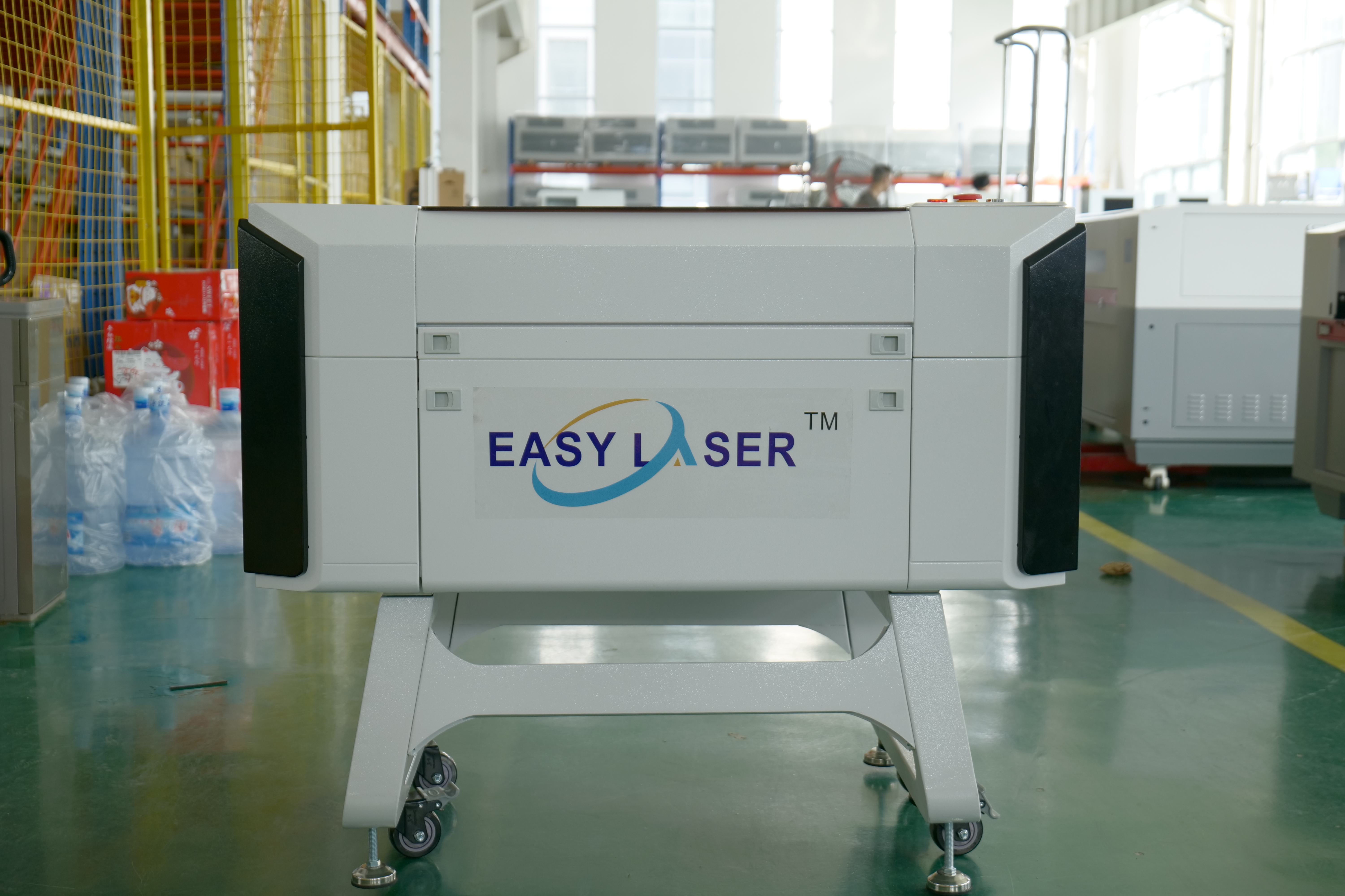
Defining the physical, optical, and operational requirements prevents batch variation. You must control several core variables to maintain identical cuts on both sides of the gantry. Ignoring even one of these variables will result in asymmetrical cutting performance. We will examine the specific mechanical and optical factors that dictate success on the shop floor.
Perfectly parallel beam paths along the X and Y axes are mandatory. A dual head CO2 laser cutter relies on precise mirror targeting. Gantry flex or micro-vibrations disproportionately affect the secondary head. This head typically sits further from the laser source. Even a slight misalignment at mirror two translates into a massive focal shift at head two. You must ensure the beam hits the exact dead center of mirror three on both heads, regardless of where the carriage is positioned on the bed.
To achieve this, operators must perform the four-corner pulse test. You place a piece of thermal target tape over the entry hole of the laser head. You move the head to the top left, pulse the laser, and mark the spot. You repeat this at the top right, bottom left, and bottom right. If the burn mark moves even a fraction of a millimeter between these four positions, your beam is not parallel to the gantry rails. You must adjust the mirror mounts until the dot remains perfectly stationary across the entire travel envelope. This process must be repeated for both the primary and secondary optical paths.
Matching the laser head and lens type to the target material impacts performance directly. You must run identical focal lens lengths on both heads. If head one uses a 2.0-inch lens, head two must use a 2.0-inch lens. Mixing focal lengths creates different laser dot sizes. Different dot sizes mean different energy densities at the workpiece. This guarantees inconsistent cutting depths. A 1.5-inch lens creates a smaller, more intense spot ideal for engraving, while a 4.0-inch lens creates a longer focal depth ideal for cutting thick foam or wood. You cannot mix these applications across two heads simultaneously.
Furthermore, the lenses must be from the same manufacturer and batch if possible. Slight variations in the curvature of the zinc selenide (ZnSe) substrate can alter the focal point by a few tenths of a millimeter. When you are trying to cut 18mm plywood consistently, a 0.2mm difference in focal height between head one and head two will result in one head failing to clear the bottom of the cut. Always replace lenses in pairs. If one lens gets scratched or clouded by back-reflection, throw it away and install two brand new lenses to maintain perfect optical parity.
Material warping ruins dual-head consistency. Consider warped plywood or uneven acrylic. If the material sits 1.5mm higher on the right side of the bed, the secondary head loses focus. It will have a larger laser dot size. This reduces energy density and fails to cut through the material. Dirty, rusted, or highly reflective materials cause back-reflection. This returns energy up the nozzle and damages the focal optics of both heads. Use honeycomb bed pinning or vacuum tables to secure materials. Independent manual or auto-focus for each head solves localized warping issues.
When dealing with flexible materials like leather or thin textiles, a vacuum bed is non-negotiable. The vacuum pulls the material flat against the honeycomb, ensuring a uniform distance from the nozzle tip to the material surface across the entire bed. If you are cutting rigid materials that have a natural bow, like Baltic birch plywood, you must use mechanical hold-downs. Pinning the edges and the center of the board forces it flat. If you cannot get the material perfectly flat, you must manually adjust the Z-axis tube of the secondary head to compensate for the height difference in that specific zone. This is why independent Z-axis adjustment on the secondary head is a critical feature for any serious production machine.
Splitting a single air compressor line to two heads involves basic fluid dynamics. You risk pressure drops at the secondary nozzle. Low pressure leads to excessive charring or flame-ups on one side of the cut. You must use identical nozzle orifices. Install inline pressure regulators for each head to maintain consistent gas velocity across both cutting zones. If head one has a 2mm nozzle opening and head two has a 3mm opening, the air velocity will be drastically different, altering the melt-shear dynamics of the cut.
Verify the main compressor output pressure exceeds the combined requirement of both heads.
Install a Y-splitter with equal length hoses running to each laser head carriage.
Mount independent flow meters and pressure regulators directly above each cutting head.
Test the air pressure at the nozzle tip using a digital manometer to ensure identical output.
Inspect the air lines weekly for kinks, leaks, or condensation buildup that could restrict flow.
Moisture in the air lines is another silent killer of cut consistency. If water droplets make it past your traps and blow through the nozzle, they will instantly vaporize upon hitting the laser beam. This creates a micro-explosion of steam that disrupts the beam profile and leaves a jagged, charred edge on the material. You must run a high-quality refrigerated air dryer in line before the air reaches the laser machine. This ensures clean, dry air is delivered equally to both cutting zones.
Software frequency adjustments (Hz) and duty cycle limits control thermal delivery. Set duty cycles between 80% and 90% for heavy cutting. Optimizing these settings prevents heat buildup in the material. Proper frequency tuning ensures both cuts share identical kerf widths and clean edges without melting the substrate. If you push a glass CO2 tube past its maximum rated duty cycle, the gas mixture inside degrades rapidly, and the beam mode shifts from a sharp point to a blurry ring.
When running two tubes, you must ensure the power supplies are calibrated to deliver the exact same milliamp (mA) current at a given software percentage. A 50% power setting in your controller might command 15mA from power supply A, but 17mA from power supply B due to internal component tolerances. You must use an inline ammeter on the cathode return line of each tube to verify the actual current draw. Adjust the trim pots on the power supplies until both tubes draw the exact same current at identical software power levels.
You need a practical, evidence-based framework for syncing two heads before running a production batch. Guesswork leads to scrapped material. Follow these mechanical and optical procedures to establish a reliable baseline.
Use a laser power meter probe at the nozzle of both heads. Document the actual wattage delivered to the workpiece. Do not rely on software percentages. Software might say 80%, but the physical output could differ by 15 watts between heads. Establish this baseline before adjusting mirrors. You need to know if you have an optical alignment problem or a raw power generation problem. If tube A outputs 100 watts at the source and 95 watts at the nozzle, but tube B outputs 100 watts at the source and 70 watts at the nozzle, you know you have a severe alignment or dirty optic issue on side B.
Perform this power test once a month. Keep a logbook attached to the machine. Record the date, the software power percentage, the mA reading on the ammeter, and the actual wattage measured at the nozzle for both heads. This historical data allows you to track tube degradation over time and predict when a replacement will be necessary, preventing unexpected downtime in the middle of a large production run.
Validate alignment at physical extremes. Move the laser carriage to the back-left limit of the gantry. Put a piece of tape there with a dot or an "X" mark. Fire a test pulse. Verify the physical path of the red dot pointer and the primary beam match perfectly. Repeat this at all four corners of the bed. The beam must hit the exact same spot on the third mirror regardless of the carriage position. If it drifts, your gantry is out of square or your mirrors are not parallel to the travel axes.
When aligning the secondary head on a dual-tube system, you must also ensure the beam enters the nozzle perfectly plumb. If the beam hits the focal lens at an angle, it will exit the nozzle at an angle. This creates a beveled cut edge on your material. To test this, place a thick block of clear acrylic under the nozzle. Fire a long pulse to drill a deep hole into the acrylic. Inspect the hole from the side. It should be perfectly vertical. If it leans to the left or right, you must adjust the tilt of the third mirror until the beam drops straight down through the center of the lens.
Set the physical distance between heads to match the software layout. If your software expects heads 300mm apart, measure and lock the physical heads at exactly 300mm. Configure your software homing behaviors and safe stop positions. Manage your "return to home" settings carefully. Disable automatic homing upon job completion. Set dedicated, safe user origins to prevent carriage crashes and multi-head offsets.
You must also account for the physical width of the secondary carriage. When the primary head moves to the far right of the bed, the secondary head will hit the right-side enclosure wall if you do not set proper soft limits in the controller. Measure the exact distance from the primary nozzle to the secondary nozzle. Enter this offset value into your DSP controller parameters. This tells the machine exactly where the second head is located, allowing it to calculate safe travel boundaries and prevent violent mechanical crashes that can destroy stepper motors and snap drive belts.
Tram the laser bed to the gantry to ensure a level working plane. Set the primary head focus using your standard focal gauge. Lock the primary head in place. Next, mechanically adjust the secondary head tube height. Slide it up or down in its mount until it matches the exact focal distance of the primary head. Lock it securely. Do not assume the bed is perfectly level. Use a dial indicator mounted to the laser carriage to sweep the entire bed surface and shim the honeycomb supports as necessary.
Once the bed is trammed, perform a ramp test for both heads simultaneously. Place a piece of anodized aluminum or painted wood on an incline under the gantry. Fire both lasers at a low power setting while moving the gantry across the incline. This will draw two fine lines on the material. Examine the lines to find the narrowest point. This is the true focal point. Measure the distance from the nozzle to the material at this exact spot for both heads. They must be identical. If they are not, adjust the secondary head barrel until the focal points match perfectly.
Scaling to a dual-head workflow introduces specific risks. Knowing how to prevent them keeps your production line moving. You must anticipate mechanical wear and optical degradation before they ruin a batch of expensive material.
Tube A might lose 15% power over six months. Tube B might only lose 5%. This uneven degradation causes one head to fail on thick materials. Implement a monthly power-meter testing schedule. Adjust software max-power limits independently. You can artificially match the output of the stronger tube to the weaker tube to maintain identical cuts. If tube A maxes out at 85 watts and tube B maxes out at 100 watts, you must cap tube B at 85% power in your controller settings. This ensures both heads deliver the same thermal energy to the material, preserving cut consistency at the cost of overall maximum speed.
Cutting dirty, contaminated, or highly reflective materials bounces laser energy back into the nozzle. This cracks or clouds the focal lens. Establish strict pre-cut material inspection protocols. Always clean, flatten, and inspect materials before placing them on the bed. Never cut bare copper, brass, or polished aluminum with a standard CO2 laser. The 10.6-micron wavelength reflects heavily off these surfaces. The reflected beam travels back up through the lens, hits the mirrors, and can even travel all the way back into the laser tube, destroying the output coupler and ruining the tube instantly.
The added weight of a second head causes micro-sag in the center of the X-axis. It also creates uneven wear on Y-axis stepper belts. Perform regular linear guide rail maintenance. Use a sonic tension meter for periodic belt tensioning. Verify the squareness of the gantry monthly. If the left Y-axis belt is tighter than the right Y-axis belt, the gantry will crab-walk down the bed. This destroys dimensional accuracy. Circles will cut as ovals, and squares will cut as parallelograms. Clean the linear rails with a degreaser and apply a light coat of lithium grease every fifty hours of operation to prevent binding and ensure smooth carriage travel.
Running two tubes requires exactly double the cooling capacity. Ensure your chiller is rated for the combined wattage of both tubes. Monitor flow sensors constantly. Inadequate cooling leads to thermal lensing in the optics and rapid tube failure. If you are running two 130-watt tubes, a standard CW-5200 chiller will not suffice. You must upgrade to a CW-6000 or higher with active freon refrigeration. The water temperature must remain stable between 18°C and 22°C. If the water temperature fluctuates, the physical dimensions of the glass tube expand and contract, which alters the beam mode and reduces cutting power.
A dual-head machine is a highly effective tool for scaling throughput. It shifts the operational burden from manual material handling to rigorous optical and mechanical calibration. When evaluating machines, prioritize heavy-duty rigid gantries and dual-tube architectures for maximum reliability. To maintain peak performance, follow these steps:
Test nozzle wattage monthly using a calibrated power probe.
Clean and inspect all beam splitters and focal lenses weekly.
Tram your cutting bed to ensure perfect Z-axis alignment across the entire gantry span.
Install independent air regulators to guarantee equal assist gas pressure at both nozzles.
A: This usually stems from optical misalignment, a dirty beam splitter, or a longer beam path causing beam divergence. Check your mirror alignment at the furthest gantry points and clean all optics thoroughly.
A: No. Using different focal lenses creates different spot sizes and energy densities. Both heads must use identical lenses to ensure consistent kerf widths and cutting depths.
A: Check belt tension monthly. The extra weight of the second carriage accelerates belt wear. Uneven tension causes the secondary head to lag, ruining dimensional accuracy.
A: Use a high-quality honeycomb bed with hold-down pins or a vacuum table. If the material warps, the focal distance changes, causing one head to lose cutting power.
A: Yes. You are splitting the air volume between two nozzles. You need a compressor capable of maintaining consistent high pressure across both lines simultaneously to prevent edge charring.
A: Install a beam expander or collimator at the laser tube output. This keeps the beam diameter consistent over long distances, ensuring the secondary head receives the same energy profile as the primary head.


