
Please Choose Your Language
Views: 0 Author: Site Editor Publish Time: 2026-10-15 Origin: Site


Does your assembly line stall due to mismatched parts? Picture the shop floor. A welder struggles to clamp two misaligned plates. An automated robotic arm halts because a metal tab refuses to fit into its designated slot. Inconsistent cuts cause severe material waste. They skyrocket manual rework hours and ultimately erode your profit margins.
Producing a single acceptable part is relatively straightforward in modern fabrication. The true engineering challenge lies in producing thousands of identical components without dimensional drift. In this post, you will learn exactly how advanced optical technology eliminates these bottlenecks. We will explore how to ensure perfectly identical parts every single time.
A standard precision laser cutter eliminates physical tool wear, guaranteeing that the final part in a high-volume production run is dimensionally identical to the first.
Achieving strict dimensional tolerances relies heavily on a combination of routine machine calibration, proper assist gas selection, and active thermal management.
Optimizing edge quality by minimizing dross and surface roughness is a critical requirement for seamless downstream part assembly.
Applying specific Design for Manufacturing principles prevents material warping and tolerance deviations during fabrication.
Selecting the appropriate equipment architecture dictates long-term operational uniformity and overall manufacturing efficiency.
Recent market analyses highlight a massive transition toward lights-out manufacturing and smart factory integration. Fabricators face tighter supply chain demands than ever before. Clients no longer tolerate acceptable defect rates. They expect zero-defect deliveries. This industry-wide push requires equipment that eliminates human error and mechanical variations.
As automated welding cells and robotic assembly become the standard, absolute part uniformity is a foundational requirement. A robotic arm lacks human intuition. It cannot manually compensate for a half-millimeter gap. Consequently, metal fabrication facilities are aggressively phasing out legacy mechanical punching. They are adopting advanced optical solutions to guarantee the micro-tolerances required by modern supply chains.
To truly master production quality, engineers must distinguish between two critical manufacturing metrics. These are accuracy and repeatability. Accuracy refers to how closely a fabricated piece matches its intended Computer-Aided Design dimensions. If an engineering drawing requires a 50.00mm square and the machine cuts a 50.02mm square, it demonstrates excellent accuracy.
Repeatability, conversely, is the equipment's ability to replicate that exact 50.02mm measurement over multiple iterations. A highly repeatable process ensures that dimensional variations between the first piece and the thousandth piece remain within an acceptable micro-tolerance range. In industrial applications, consistency is synonymous with repeatability.
When a fabrication process lacks repeatability, the financial and operational impacts compound rapidly. Variations in dimensions directly trigger severe bottlenecks in downstream processes.
Manufacturing Stage | Impact of Inconsistent Parts | Resulting Business Cost |
|---|---|---|
Welding | Poor joint fit-up, requiring excessive filler material or manual clamping. | Increased labor hours and a significantly higher risk of structural weld failure. |
Assembly | Misaligned fastener holes and interlocking tabs that refuse to fit together. | High scrap rates, tedious manual rework, and delayed production schedules. |
Quality Assurance | Higher rejection rates during final tolerance inspections. | Wasted raw material and bloated inspection overhead. |
Investing in highly repeatable technology mitigates these risks. It stabilizes the entire production workflow and protects the bottom line.
Traditional mechanical cutting methods inherently struggle with long-term consistency. Stamping, punching, and milling degrade over time due to the physical nature of their operation. A precision laser cutting machine fundamentally changes this dynamic by entirely removing friction from the equation.
The most profound advantage of optical processing is its non-contact nature. Mechanical cutting tools experience severe friction with every single cycle. Over time, blades dull, punches wear down, and dies lose their sharp edges. This physical degradation causes a gradual, often unnoticed shift in dimensions. Engineers refer to this as tool wear drift.
Optical systems utilize a focused beam of high-density light to melt and vaporize metal. There is zero physical contact between the machine head and the workpiece. The absence of friction means there is absolutely no tool wear. The beam profile remains constant, allowing the facility to deliver absolute uniformity across massive production runs.
Modern equipment is driven by sophisticated Computer Numerical Control architectures. These systems utilize high-resolution servo motors, rigid linear guides, and precise rack-and-pinion drives. With positioning accuracies often reaching ±0.03mm and repeatability hovering around ±0.02mm, the system executes complex geometric paths flawlessly.
Furthermore, closed-loop feedback systems constantly monitor the exact position of the cutting head. By making micro-adjustments in real-time, the machine ensures the physical movement perfectly mirrors the digital file. This eliminates human error from the motion profile.
When raw metal is exposed to intense heat, it naturally expands. Its internal metallurgical structure alters. The specific area affected by this thermal shock is called the Heat-Affected Zone. Large heat zones lead to severe material warping. This instantly destroys part consistency.
Advanced technology concentrates thermal energy into a microscopic focal spot. The energy is delivered so rapidly that the surrounding metal simply does not have time to absorb excess heat. This highly localized energy transfer results in an incredibly narrow heat zone. It prevents thermal distortion and ensures the component remains flat upon cooling.
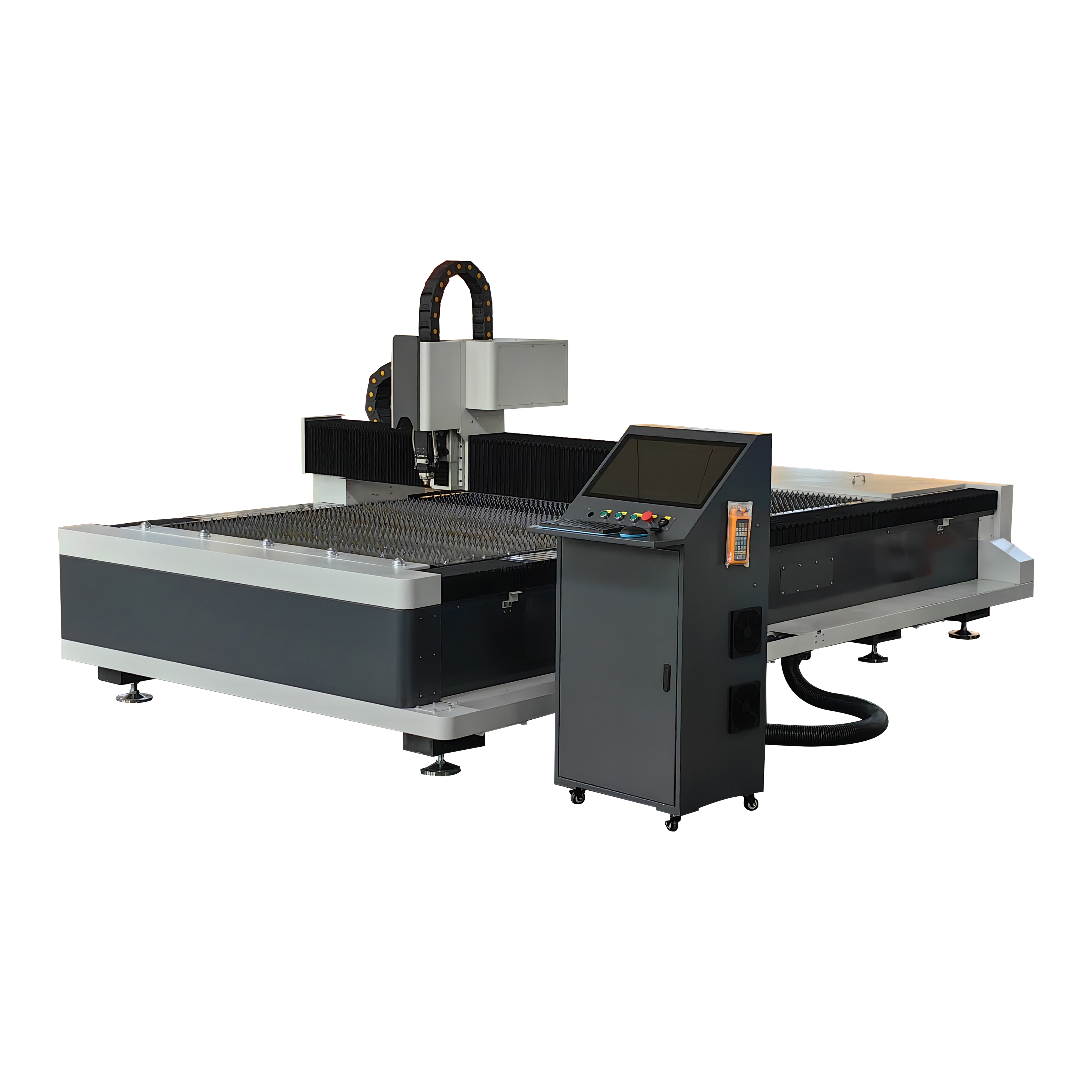
While optical technology is inherently precise, maintaining that precision requires strict control over several operational variables. Achieving accurate metal cutting is not a passive task. It is a continuous process of calibration and material management.
The accuracy of any cutter is directly tied to the pristine condition of its optical and mechanical components. Routine calibration is non-negotiable for consistent output. Operators must ensure that the beam is perfectly aligned through the dead center of the copper nozzle. A misaligned beam will cause angled edges and fluctuating kerf widths depending on the direction of travel.
Additionally, protective lenses must be kept spotless. Even a microscopic dust particle can scatter the light. This reduces power density and shifts the focal point. This thermal lensing effect immediately degrades cut uniformity.
The kerf represents the exact amount of material removed by the beam during the process. This typically ranges from 0.1mm to 0.3mm, depending on material thickness and focus settings. To achieve exact final dimensions, programming software must apply precise kerf compensation. The software automatically offsets the cutting path by half the width of the kerf.
If kerf width fluctuates due to inconsistent power delivery or erratic speeds, the final dimensions will vary. Maintaining a stable kerf is critical for repeatable accuracy.
The consistency of the raw sheet metal heavily impacts the final result. Variations in material thickness, surface rust, or unrelieved internal stresses from the steel rolling process can cause highly unpredictable behaviors mid-cut.
Modern systems utilize capacitive height-sensing nozzles. These automatically adjust the Z-axis to maintain a constant focal distance, even if the sheet metal is slightly warped. Nevertheless, for the highest level of consistency, utilizing high-quality, stress-relieved sheet metal with a uniform surface finish is strongly recommended.
In many manufacturing environments, a component is only considered acceptable if its edge quality meets strict engineering standards. Rough edges or accumulated slag prevent interlocking tabs from fitting together correctly. This effectively ruins assembly consistency.
Edge quality is generally evaluated by two primary metrics. These are surface roughness striations and dross accumulation. Roughness refers to the vertical lines left on the cut edge. Lower roughness values indicate a smoother, cleaner edge. Dross, or slag, is the resolidified molten metal that stubbornly clings to the bottom edge of the cut.
For instance, when an operator sets the focal point too high on a thick mild steel plate, the bottom of the cut will inevitably accumulate thick dross. Removing inconsistent dross requires manual grinding. This introduces human error and physically alters the final dimensions of the part, thereby destroying repeatability.
Assist gases are blown through the nozzle alongside the beam. They aggressively clear molten material from the kerf. The strategic choice of gas drastically affects edge consistency.
Oxygen: Primarily used for thick carbon steel. It creates an exothermic reaction that speeds up the cut but leaves a thin oxide layer that may require chemical removal before painting.
Nitrogen: Ideal for stainless steel and aluminum. It provides an inert cutting environment, leaving a clean, bright, oxidation-free edge that requires zero secondary processing.
Compressed Air: Used for thin sheet metals to achieve fast cutting speeds at a very low cost, though it leaves a slight burr and minimal oxidation.
For highly repeatable assembly lines, Nitrogen is often the preferred choice. It completely eliminates the need for manual post-processing, ensuring the edge remains exactly as the machine cut it.
The focal point must be precisely positioned relative to the material surface. For thin metals, the focus is typically set directly on the surface. Conversely, for thicker metals, it is driven below the surface to ensure a uniform, stable melt pool.
If the speed is too fast, the beam drags backward. This causes incomplete penetration and heavy dross. If the speed is too slow, excessive heat builds up in the localized area. This causes a wider kerf and severe edge roughness. Dialing in the optimal speed-to-power ratio is critical for maintaining a uniform edge profile across an entire sheet.
Achieving absolute part consistency does not rely solely on the equipment. It begins in the engineering department. Design for Manufacturing principles are critical when utilizing optical cutting systems. Even the most advanced systems cannot compensate for geometries that inherently invite thermal distortion. By adhering to standardized design rules for fine metal laser cutting, engineers can ensure that every piece off the bed matches the original model perfectly.
One of the most common causes of part rejection is improper hole sizing. When a laser pierces metal, it generates intense localized heat. If a hole is too small relative to the material thickness, the heat cannot dissipate fast enough. This leads to a blowout, which is a localized melting that ruins the hole tolerance and shape.
As a general engineering rule, the minimum hole diameter should be equal to or greater than the thickness of the material. This one to one ratio works well for mild and stainless steel. For highly thermally conductive materials like aluminum, a safer ratio of 1.2 to 1 is often recommended to prevent heat saturation.
Webbing refers to the solid material left between two adjacent cuts. Bridging refers to the material connecting the main body to internal features. If these sections are designed too thin, the heat zones from the adjacent cuts will overlap. This overlapping heat causes the narrow web to warp, melt, or lose its structural integrity completely.
To maintain structural consistency, webs and bridges should generally be no narrower than the thickness of the material itself. For materials thicker than 5mm, increasing the web width to 1.5 times the thickness provides a robust margin against thermal distortion.
Metals expand when exposed to intense heat and contract as they cool. When cutting long, narrow parts or highly intricate geometries with asymmetrical features, this rapid thermal cycling can cause the part to bow or twist mid-cut. By the time the cutting head finishes the profile, the material has physically shifted on the slats, resulting in severe tolerance deviations.
To mitigate this, designers should incorporate stress-relief cuts. They can also distribute heat evenly by utilizing a staggered cutting sequence. Avoiding long, continuous linear cuts on thin materials helps manage the thermal load, ensuring the final piece remains flat.
Even with top-tier equipment and rigorous design practices, operators may occasionally encounter deviations. Systematic troubleshooting is essential. You must identify whether the root cause is mechanical, optical, or related to programming. Below is an analytical approach to resolving the most common consistency issues on the shop floor.
When a previously stable production run suddenly yields components that are out of tolerance, operators often panic. However, a systematic checklist isolates the problem rapidly.
Focal Lens Contamination: A microscopic speck of dust on the protective window absorbs laser energy. This triggers thermal lensing, which shifts the focal point mid-cut, widening the kerf and altering dimensions.
Mechanical Backlash: Over time, the drive belts or linear guides may develop slack. This mechanical backlash prevents the gantry from returning to its exact zero-point, causing shifting geometries.
Nozzle Alignment: Perform a simple tape-shot test. If a collision has slightly misaligned the nozzle, the gas flow will be asymmetrical. This pushes the beam and alters the cut path.
If parts are warping while still on the cutting bed, the primary culprit is excessive heat accumulation. This is frequently a programming issue rather than a machine fault. The most effective solution is adjusting the cutting sequence.
Operators should always program the machine to cut internal features before the outer contour. If the outer contour is cut first, the part becomes physically detached from the main sheet. It loses its ability to dissipate heat into the surrounding thermal mass. Additionally, utilizing tiny uncut tabs keeps the part securely anchored to the heavy skeleton during the process. This prevents it from bowing up and colliding with the cutting head.
A highly frustrating issue for fabricators is when parts cut on the left side of the sheet exhibit perfect, smooth edges, while parts on the right side suffer from heavy dross and severe striations. This inconsistency almost always points to an unlevel cutting bed or a beam alignment issue across the working envelope.
If the bed is not perfectly parallel to the gantry travel path, the focal distance will drift as the head moves. Regular bed leveling and optical alignment are mandatory for maintaining uniformity across the entire working area.
Investing in the correct capital equipment is the ultimate determinant of your production consistency. The specification of the machine must align precisely with your material types, thickness requirements, and facility conditions.
In high-precision manufacturing, the ambient environment plays a critical role. Airborne dust, temperature fluctuations, and shop floor drafts can affect the optical path and assist gas dynamics. Fully enclosed machines isolate the cutting process. This ensures that thermal conditions remain stable and prevents particulate matter from settling on the raw material. For operations demanding the highest level of stability and operator protection, implementing a closed-type precision system is a strategic decision that directly protects part consistency.
Processing thick plate metal, such as 15mm to 25mm carbon steel, presents unique consistency challenges. If a machine lacks sufficient wattage, the operator must drastically reduce the cutting speed to penetrate the material. This slow speed pumps an immense amount of heat into the plate. It causes massive thermal distortion and severe edge tapering, creating a V-shaped cut rather than a straight 90-degree edge. Upgrading to a 6000w high-power fiber system ensures the beam has sufficient energy to vaporize material instantly. This maintains strict dimensional tolerances even in heavy-duty applications.
Not all manufacturing requires processing massive sheet metal. Industries such as medical device manufacturing, electronics, and jewelry require extreme micrometer-level precision on very small footprints. Using a massive gantry system for tiny, intricate parts can sometimes introduce unnecessary mechanical inertia. Compact machines, such as a 60x60cm 1500w to 2000w system, are engineered with highly rigid, scaled-down frames. This eliminates vibration, allowing the control system to execute rapid, minute directional changes flawlessly.
Modern fiber laser systems are highly accurate, typically holding tolerances between ±0.05mm and ±0.1mm. The exact tolerance achieved depends heavily on the material type, the thickness of the sheet, and the structural rigidity of the machine gantry system.
Yes. As material thickness increases, it becomes more susceptible to edge tapering and thermal distortion. High-power lasers are required to cut thick plates fast enough to minimize the heat-affected zone and maintain a straight, consistent, and perpendicular edge.
To ensure absolute repeatability, operators should perform daily checks on the protective lenses and nozzle centering. Weekly maintenance should include checking optical alignments and assist gas pressures. Comprehensive mechanical checks, such as inspecting belt tension and bed leveling, should be conducted monthly.
Yes. Unlike older CO2 lasers, which struggled with back-reflections, modern fiber lasers operate at a 1064nm wavelength. This wavelength is readily absorbed by highly reflective metals like aluminum, brass, and copper, allowing for consistent cutting without risking damage to the internal optics.
By producing parts with exceptionally smooth edges and tight tolerances, advanced cutting systems eliminate the need for downstream grinding, deburring, or mechanical straightening. When using Nitrogen as an assist gas, the cut edges are oxidation-free, meaning parts can go directly to the welding or painting departments without chemical cleaning.
Assist gas pressure and purity dictate the stability of the molten pool inside the kerf. Fluctuations in gas pressure cause irregular clearing of molten metal, leading to random dross buildup. Consistent gas delivery ensures identical edge profiles from the first part to the last.
To achieve the micro-tolerances required by modern supply chains, upgrading your shop floor with the right technology is essential. Whether you need a compact system for intricate designs, a fully enclosed unit for environmental control, or a high-power machine for thick plates, selecting engineered solutions tailored to your production prevents bottlenecks before they start. Explore the full range of professional equipment at Easy CNC Laser to find the exact specifications that match your manufacturing demands.


